System and method for testing multi-user parallel of locomotive switch power supply

A switching power supply and test system technology, applied in the field of locomotive switching power supply multi-user parallel test system, can solve the problems of resource surplus, low resource utilization rate, and switching power supply cannot be tested at the same time, so as to improve the utilization rate and test throughput rate Effect

Inactive Publication Date: 2012-09-19
ZHUZHOU CSR TIMES ELECTRIC CO LTD
View PDF6 Cites 6 Cited by
  • Summary
  • Abstract
  • Description
  • Claims
  • Application Information

AI Technical Summary

Problems solved by technology

[0003] (1) The test system has relatively rich resources. When testing a specific locomotive switching power supply, the test system only uses a part of the resources, and the rest of the resources are idle, so the utilization rate of the test system resources is not high;
[0004] (2) At the same time, even if some switching power supplies with less resource requirements cannot be tested at the same time, they can only wait
[0007] (1) The resource utilization rate is not high. When only testing each type of locomotive switching power supply, the resources of the locomotive switching power supply test system are left (unused) to varying degrees;
[0008] (2) Only one locomotive switching power supply can be tested at a time, even if the remaining resources meet the requirements, it can only wait;
[0009] (3) Only one person is allowed to use the test resources of the locomotive switching power supply test system at the same time

Method used


Image

  • System and method for testing multi-user parallel of locomotive switch power supply
  • System and method for testing multi-user parallel of locomotive switch power supply
  • System and method for testing multi-user parallel of locomotive switch power supply

Examples


specific Embodiment approach

[0038] A specific implementation of the method for performing multi-user parallel testing of the locomotive switching power supply by using the above-mentioned multi-user parallel testing system for the switching power supply of the locomotive, comprising the following steps:

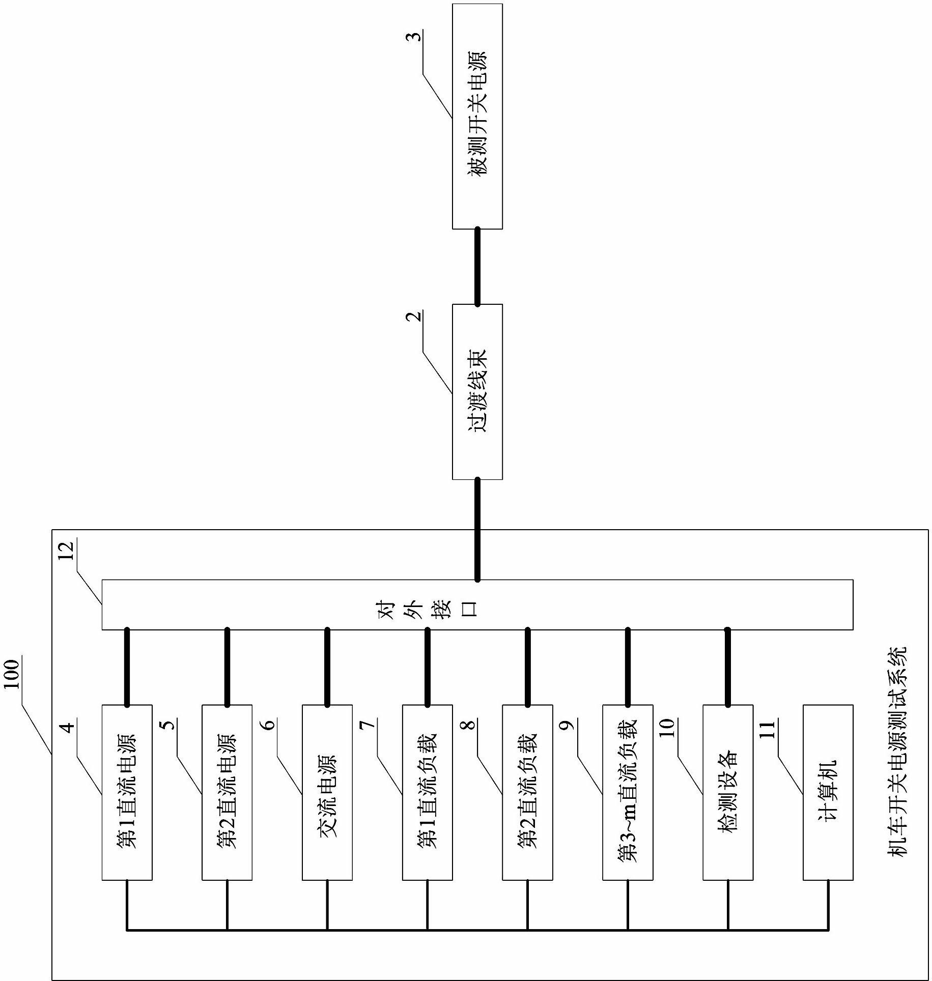
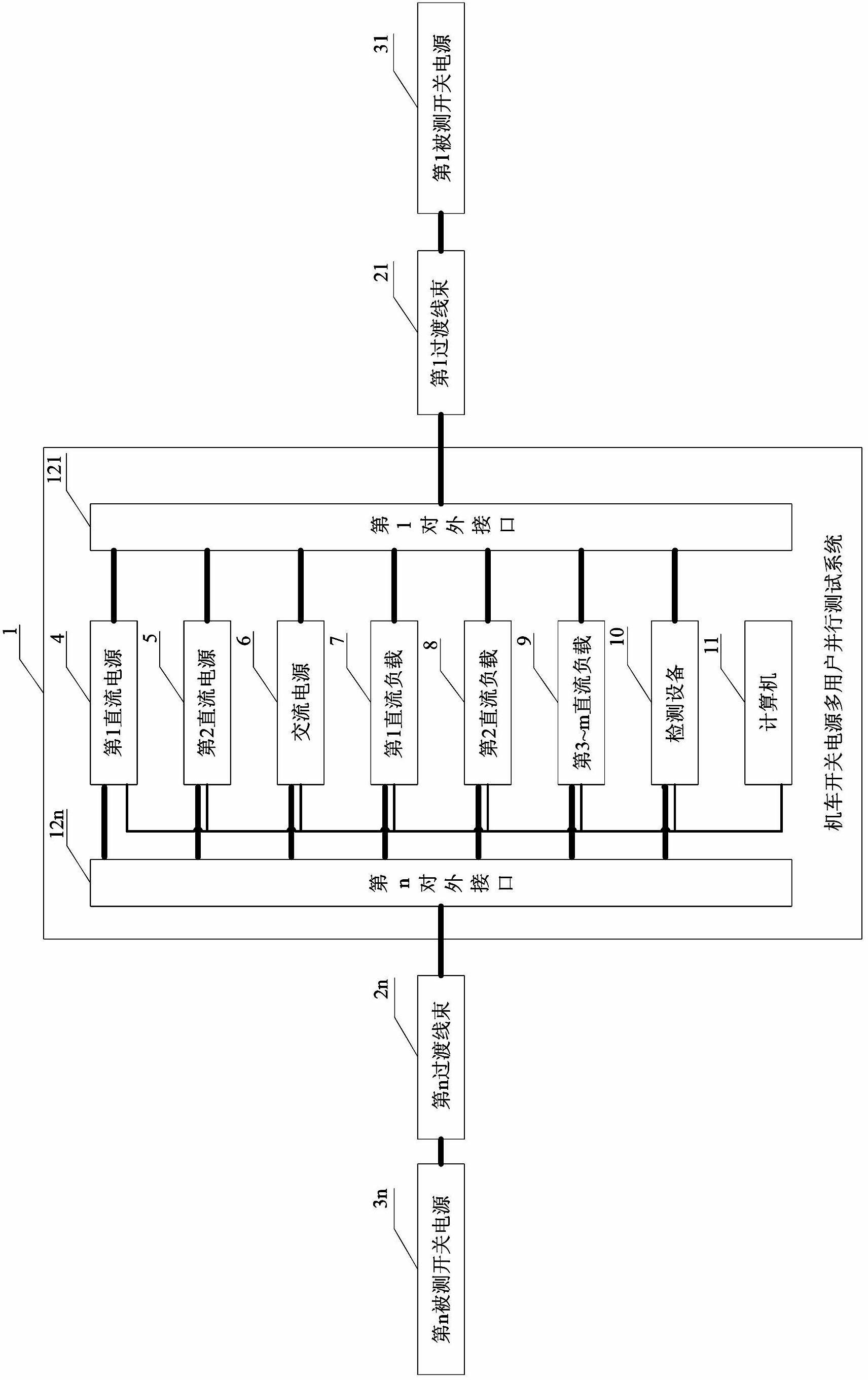
[0039] S100: All users jointly occupy the host computer 13 of the computer 11 in the multi-user parallel test system 1 for the switching power supply of the locomotive, and the multi-user parallel test system 1 for the switching power supply of the locomotive includes the first DC power supply 4, the second DC power supply 5, the AC power supply 6, Test resources including the first DC load 7, the second DC load 8, the 3rd to m DC loads 9 and the testing equipment 10;

[0040] S101: Each user enjoys the control rights of the assigned graphics card, monitor, keyboard and mouse respectively, and has no control rights to the graphics cards, monitors, keyboards and mice of other users (the setting of the con...


PUM


Abstract

The invention discloses a system and a method for testing multi-user parallel of a locomotive switch power supply. A first direct current power supply, a second direct current power supply, an alternating current power supply, a first direct current load, a second direction current load, third to mth direct current loads and a detecting device are connected through a control bus; and n external interfaces are connected with the first direct current power supply, the second direct current power supply, the alternating current power supply, the first direct current load, the second direction current load, the third to the mth direct current loads and the detecting device through a lead and is connected with a computer through a control bus. The value of m is determined according to a maximum value of output numbers of the power supply of the switch to be tested; and n external interfaces are connected with the power supplies of n switches to be tested through n transition harnesses. A multi-user configuration mode is adopted in the computer and the computer comprises a plurality of user configuration modules. With the adoption of the system and the method, the technical problems that resource utilization rate is not high in the prior art, only one switch power supply of the locomotive is tested at one time and only one person is allowed to use the resource of a locomotive switch power supply testing system at one moment are solved.

Description

technical field [0001] The invention relates to an electrical testing system and a method thereof, in particular to a multi-user parallel testing system and method for a locomotive switching power supply applied to electrified rail transit equipment. Background technique [0002] The current locomotive switching power supply has the following characteristics: (1) There are two types of input: AC (alternating current) and DC (direct current); (2) The input voltage, input undervoltage protection value, and input overvoltage protection value of different locomotive switching power supplies are different. And the difference is very large; (3) The output voltage of different locomotive switching power supplies is different and the requirements for load are different; (4) The number of output voltage circuits of different locomotive switching power supplies is different, and the difference is very large. In order to adapt to these characteristics of the locomotive switching power ...

Claims


Application Information

Patent Timeline
Patent Type & Authority Applications(China)
IPC IPC(8): G01R31/40G01R31/42
Inventor 曹金洲陈志漫苏建辉余志涛李涛高峰耶小方黄进一彭真屈宏涛
Owner ZHUZHOU CSR TIMES ELECTRIC CO LTD
Why Eureka
Try Eureka