
Vehicle mounted highway network toll collection equipment and application method thereof

A device and road network technology, which is applied in the field of vehicle-mounted road network charging equipment, can solve problems such as wireless signal attenuation, 5.8GHz wireless signal attenuation, and vehicle-mounted electronic tags that cannot enter the transaction state, so as to improve reliability and safety and promote development. Effect

Active Publication Date: 2012-09-19
SHENZHEN GENVICT TECH
View PDF6 Cites 0 Cited by
  • Summary
  • Abstract
  • Description
  • Claims
  • Application Information

AI Technical Summary

Problems solved by technology

Since vehicle-mounted electronic tags are usually installed on car windows and communicate with the outside world through the window glass, however, the glass containing metal materials will cause the attenuation of the 5.8GHz wireless signal, and some vehicles (especially high-end cars) are installed with bulletproof tags. Special glass makes the 5.8GHz wireless signal attenuation more severe
Therefore, when these vehicles pass through the ETC dedicated channel, due to the severe attenuation of the 5.8GHz wireless signal, the receiving device installed in the vehicle electronic tag cannot receive enough signals, that is, the vehicle electronic tag cannot be awakened, resulting in the inability of the vehicle electronic tag to enter trading status

Method used


Image

  • Vehicle mounted highway network toll collection equipment and application method thereof
  • Vehicle mounted highway network toll collection equipment and application method thereof
  • Vehicle mounted highway network toll collection equipment and application method thereof

Examples


Embodiment Construction

[0024] The specific implementation of the vehicle-mounted road network toll collection device will be further described in detail below in conjunction with the accompanying drawings:

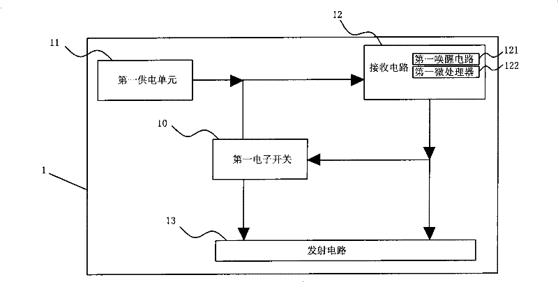
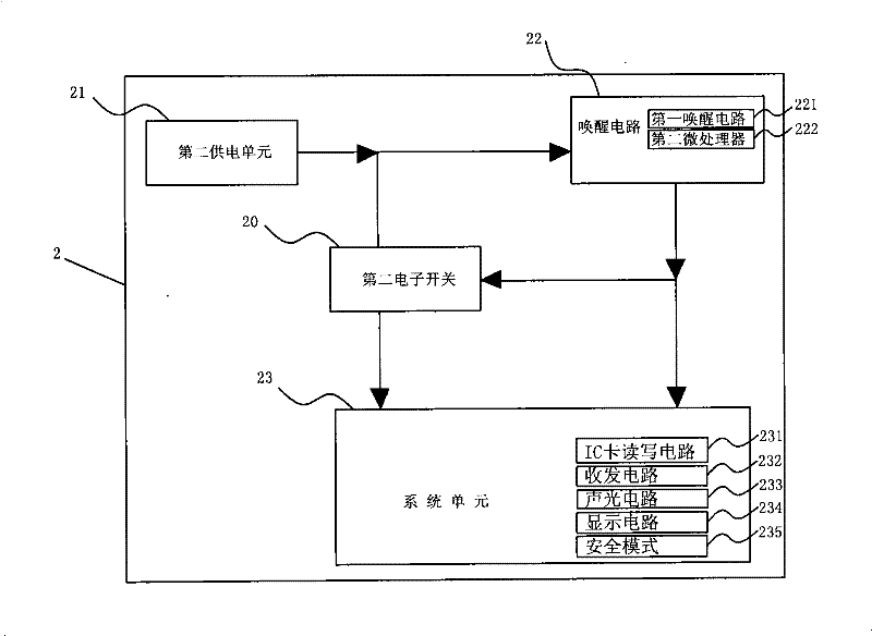
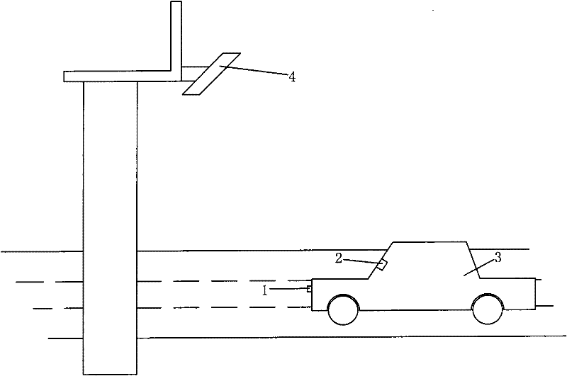
[0025] Such as Figure 1 to Figure 3 As shown, the vehicle-mounted road network toll collection device of the patent of the present invention includes two parts: the first part: a relay device 1 installed outside the vehicle 3, and the relay device 1 includes a front-end wireless signal received by the microwave read-write antenna 4 on the toll station platform. The receiving circuit 12 and the transmitting circuit 13 for sending the wake-up signal; the second part: the electronic tag 2 installed inside the vehicle 3, the electronic tag 2 includes a wake-up circuit 22 and a system unit 23 for receiving the wake-up signal, and the wake-up circuit 22 is used for receiving The wake-up signal sent by the transmitter circuit 13 of the relay device.

[0026] The circuit principle block diagram of rel...


PUM


Abstract

The invention relates to vehicle mounted highway network toll collection equipment. The vehicle mounted highway network toll collection equipment comprises a relay device and an electronic label, wherein the relay device is mounted outside a vehicle; the electronic label is mounted inside the vehicle; the relay device comprises a receiving circuit and a transmitting circuit, wherein the receiving circuit is used for receiving a front-end wireless signal and the transmitting circuit is used for transmitting an awakening signal; the electronic label comprises an awakening circuit and a system unit; and the awakening circuit receives the awakening signal transmitted by the transmitting circuit of the relay device. In the equipment, an independent wireless communication relation with strong penetrating power and diffraction power is established between the electronic label and the relay device; by using the relay device, the received 5.8GHz front-end wireless signal is transmitted to the electronic label after being converted into the 433MHz awakening signal; the electronic label is awakened by receiving the 433MHz awakening signal to enter a transaction state; and within the range of a vehicle body, the 433MHz awakening signal can penetrate or diffract through a vehicle glass made of a special material, so that the electronic label can communicate with roadside reading and writing equipment so as to guarantee safe, real-time and effective highway network toll collection transaction.

Description

technical field [0001] The invention relates to a vehicle-mounted road network charging device, in particular to a charging device in an ETC system. Background technique [0002] At present, the road network charging methods mainly include traditional manual charging, semi-automatic charging using contact IC cards, and non-stop charging using the ETC system. The ETC system is the road network charging method with the highest degree of automation and the highest charging efficiency. The ETC system is used in the highway toll gates where the number of vehicles is increasing, which greatly improves the toll speed and allows vehicles to pass quickly; compared with the traditional manual toll collection, the ETC system reduces the traffic caused by the inefficiency of manual toll collection and semi-automatic toll collection methods. Congestion, thereby reducing the operating pressure of the road network and improving the operating efficiency of the road network; its efficiency a...

Claims


Application Information

Patent Timeline
Patent Type & Authority Applications(China)
IPC IPC(8): G07B15/06
Inventor 李怀山向涛
Owner SHENZHEN GENVICT TECH
Learn More