Pulling and plugging device of R pin needle of glass isolator

A technology of glass insulators and pins, applied in pliers, overhead line/cable equipment, manufacturing tools, etc., can solve the problems of easy damage, time-consuming and labor-intensive work, poor work safety, etc., and achieve convenient manufacturing, safe use, and simple structure Effect

A technology of glass insulators and pins, applied in pliers, overhead line/cable equipment, manufacturing tools, etc., can solve the problems of easy damage, time-consuming and labor-intensive work, poor work safety, etc., and achieve convenient manufacturing, safe use, and simple structure Effect

CN102684104AActive Publication Date: 2012-09-19DANDONG ELECTRIC POWER SUPPLY COMPANY OF STATE GRID LIAONING ELECTRIC POWER SUPPLY +1

Image

  • Pulling and plugging device of R pin needle of glass isolator
  • Pulling and plugging device of R pin needle of glass isolator
  • Pulling and plugging device of R pin needle of glass isolator

Examples


Embodiment Construction

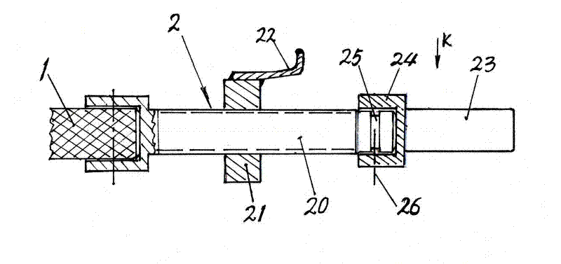
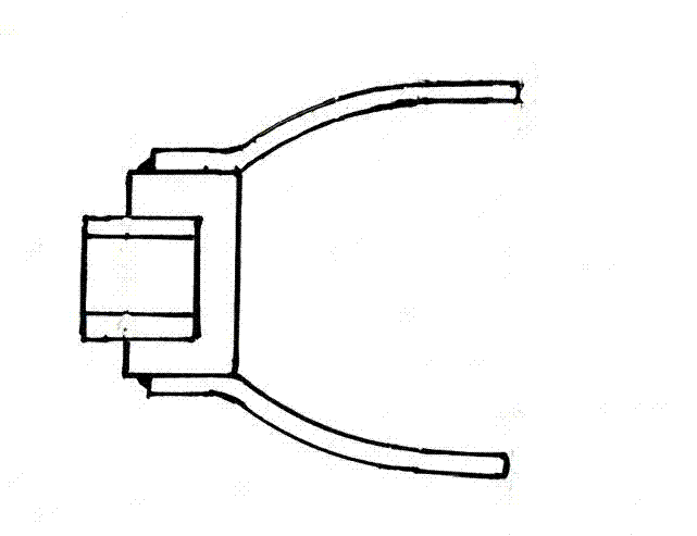
[0008] The present invention consists of an insulating rod 1, which is connected and installed at the end of the insulating rod pull Pin head 2 or pin head 3; or installed on the two ends of insulating rod 1 respectively pull The pin head 2 and the pin head 3 are formed; pull Pin device head 2 is by screw rod 20, the nut cover 21 that cooperates with screw rod 20, is welded on the nut cover 21 pull Pin 22, rotate and fit the fork 23 installed on the end of the screw rod 20, the fork 23 rotates and cooperates with the end of the screw rod 20 through the sleeve part 24 at its rear end, and has a positioning chute 25 on the end of the screw rod 20. The sleeve part 24 of the clamping fork 23 is provided with a positioning screw 26 to cooperate with the positioning chute 25, and the rear end of the screw rod 20 is fixedly connected with the insulating rod 1;

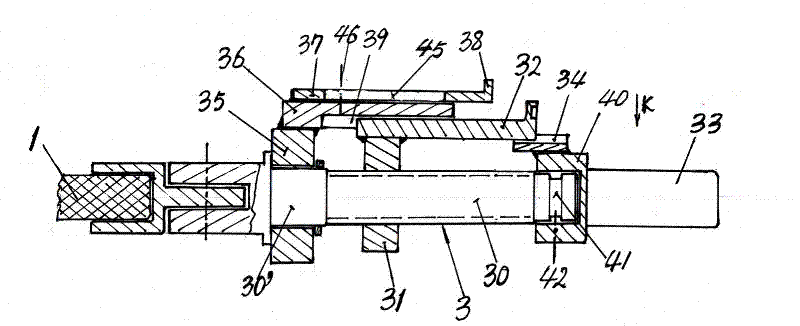
[0009] The plug head 3 comprises a screw rod 30, a nut cover 31 cooperating with the screw rod 30, and a nut cove...


PUM


Abstract

The invention discloses a pulling and plugging device of an R pin needle of a glass isolator. The pulling and plugging device comprises an insulating rod (1), a pin puller head (2) or a bolt inserter head (3) connected and arranged on the end part of the insulating rod, or a pin puller head (2) and bolt inserter head (3) respectively arranged on two ends of the insulating rod (1). The pulling and plugging device has the advantages of convenience for manufacture, safety in using, convenience, time and labor saving, no need of suspension operation of constructors, and capability of hot-line work; and the personal can carry out earth potential working without being necessarily close to an electrified body, and stably pulls or plugs the R pin needle out or in.

Description

Technical field [0001] The present invention involves an appliance for pulling or inserting the R -sales needles on the glass insulator of the tower and the high -voltage transmission line on the electric pole. Background technique [0002] The glass insulator of the high -voltage transmission line on the tower and the electric pole requires maintenance as soon as the damage is damaged. If the damage part is replaced, the R -sales needle needle on the glass insulator needsInsert the R -sales needle. [0003] The existing technology does not have a tool for pulling out and inserting the R -sales needle needle. The completion of the glass insulator R sales of the needle is completely hand -made by the construction personnel.Worked efforts, poor work safety, and it is easy to damage the glass insulator again. When the line is charged, the construction staff is the equivalent of the potential to pull out and insert the work. Invention content [0004] The purpose of the present inve...

Claims


Application Information

Patent Timeline
19 Sep 2012
Publication
CN102684104A
IPC
H02G1/02; B25B7/08
Inventors
都兴凯; ιƒζ˜ŽεΏ—