
Charge pump circuit

A charge pump and circuit technology, applied in the direction of conversion equipment without intermediate conversion to AC, can solve the problems of output voltage ripple, large quiescent current, application influence, etc., and achieve the effect of reducing quiescent current

Inactive Publication Date: 2012-09-19
SHANGHAI AWINIC TECH CO LTD
View PDF3 Cites 20 Cited by
  • Summary
  • Abstract
  • Description
  • Claims
  • Application Information

AI Technical Summary

Problems solved by technology

[0008] However, the current portable devices usually require the charge pump circuit to have greater drive capability and smaller output voltage ripple, which requires the charge pump to have a high operating frequency and a large switch area, so its quiescent current is also large. must be very large, therefore, the use of a charge pump with a smaller drive capability in method (1) obviously cannot meet the current needs
The disadvantage of method (2) is: if the operating frequency of the charge pump is low and the output load is relatively large, the output voltage ripple will be large, which will affect the application and cannot meet the current needs.

Method used


Image

  • Charge pump circuit
  • Charge pump circuit
  • Charge pump circuit

Examples


Embodiment Construction

[0055] As described in the background art, the charge pump circuit in the prior art still has a relatively large quiescent current in the standby state, so that the overall quiescent current of the portable device is relatively large, thereby affecting the standby time of the device.

[0056] In order to solve the above problems, improvements are usually made by reducing the driving capacity of the charge pump or reducing its operating frequency. However, the use of a charge pump with a small driving capacity obviously cannot meet the current market demand, and reducing the operating frequency of the charge pump will lead to When the load is large, the output voltage ripple is large, which affects the application.

[0057] The quiescent current of the charge pump circuit refers to the current consumed by the system itself when it is not loaded in the standby state. The quiescent current of the charge pump circuit is mainly composed of two parts, one part is the inherent collec...


PUM


Abstract

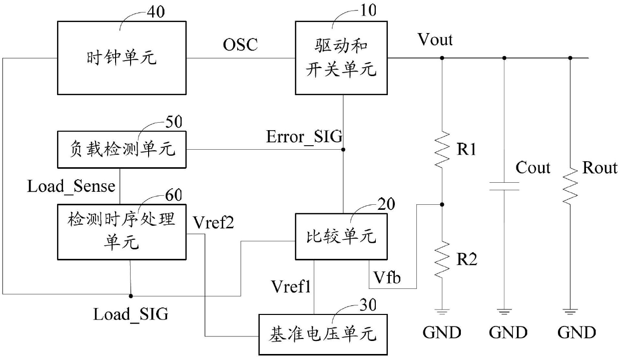
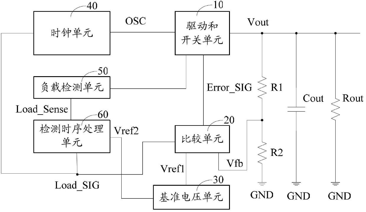
The invention relates to a charge pump circuit, which comprises a drive and switch unit, a comparison unit, a load detection unit, a detection time sequence processing unit and a clock unit; the drive and switch unit is used for performing the voltage transformation on the basis of a clock signal and a comparison result and outputting the output voltage; the comparison unit is used for comparing a feedback voltage with a first benchmark voltage and outputting the comparison result to the drive and switch unit; the feedback voltage is correlated to the output voltage; the load detection unit is used for detecting a load electric parameter of the charge pump circuit and outputting a load information signal; the detection time sequence processing unit is used for receiving the load information signal and outputting a load judging signal; the load judging signal is correlated to a working mode of the charge pump circuit; the clock unit is used for receiving the load judging signal and outputting a clock signal, the clock signal is a first clock signal or a second clock signal, and the frequency of the first clock signal is higher than that of the second clock signal. Due to the adoption of the charge pump circuit, the static current of the charge pump circuit can be effectively reduced.

Description

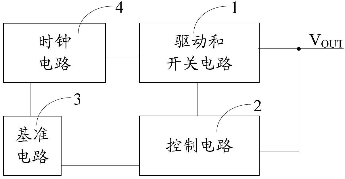
technical field [0001] The present invention relates to the technical field of electronic circuits, in particular to a charge pump circuit. Background technique [0002] Charge pump circuits are often used as power converters in battery powered portable devices. A typical charge pump circuit such as figure 1 shown. [0003] refer to figure 1 , the charge pump circuit includes: a drive and switch circuit 1 , a control circuit 2 , a reference circuit 3 and a clock circuit 4 . The driving and switching circuit 1 consists of a series of controlled switching networks and one or two charge storage capacitors (also called pump capacitors), which transfer energy by charging and discharging the charge storage capacitors. and storage to achieve boost. The reference circuit 3 is used to provide different reference voltages to the control circuit 2 and the clock circuit 4 . The clock circuit 4 supplies the drive and switch circuit 1 with a clock signal. [0004] The working princ...

Claims


Application Information

Patent Timeline
Patent Type & Authority Applications(China)
IPC IPC(8): H02M3/07
Inventor 梁仲凯万幸张海军郭辉张振浩
Owner SHANGHAI AWINIC TECH CO LTD
Learn More