
Method for calibrating detector data of an x-ray detector and x-ray imaging system

A technology of a photographing system and a detector, which is applied in the field of X-ray photographing systems, can solve problems such as high overhead of detectors, and achieve the effect of avoiding artifacts

Active Publication Date: 2016-01-20
SIEMENS HEALTHCARE GMBH
View PDF3 Cites 0 Cited by
  • Summary
  • Abstract
  • Description
  • Claims
  • Application Information

AI Technical Summary

Problems solved by technology

This places extremely high demands on the choice and quality of the detector materials used, which in turn leads to a high outlay for the corresponding detectors

Method used


Image

  • Method for calibrating detector data of an x-ray detector and x-ray imaging system
  • Method for calibrating detector data of an x-ray detector and x-ray imaging system
  • Method for calibrating detector data of an x-ray detector and x-ray imaging system

Examples


Embodiment Construction

[0040] figure 1 A schematically illustrated signal characteristic of a detector material with a previous dose load is shown. The time t is plotted on the abscissa, but here too is proportional to the applied dose since the detector is irradiated at the same intervals with the same dose. The relative signal characteristic (corresponding to drift) of the detector S / S is plotted on the ordinate 0 Curve 1, where S represents the current signal response to a specific dose rate, and S0 Indicates the initial signal response for this dose rate.

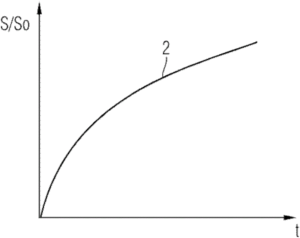
[0041] figure 2 The relative signal characteristic S / S of the same detector is shown 0 Curve 2 with respect to recovery time t.

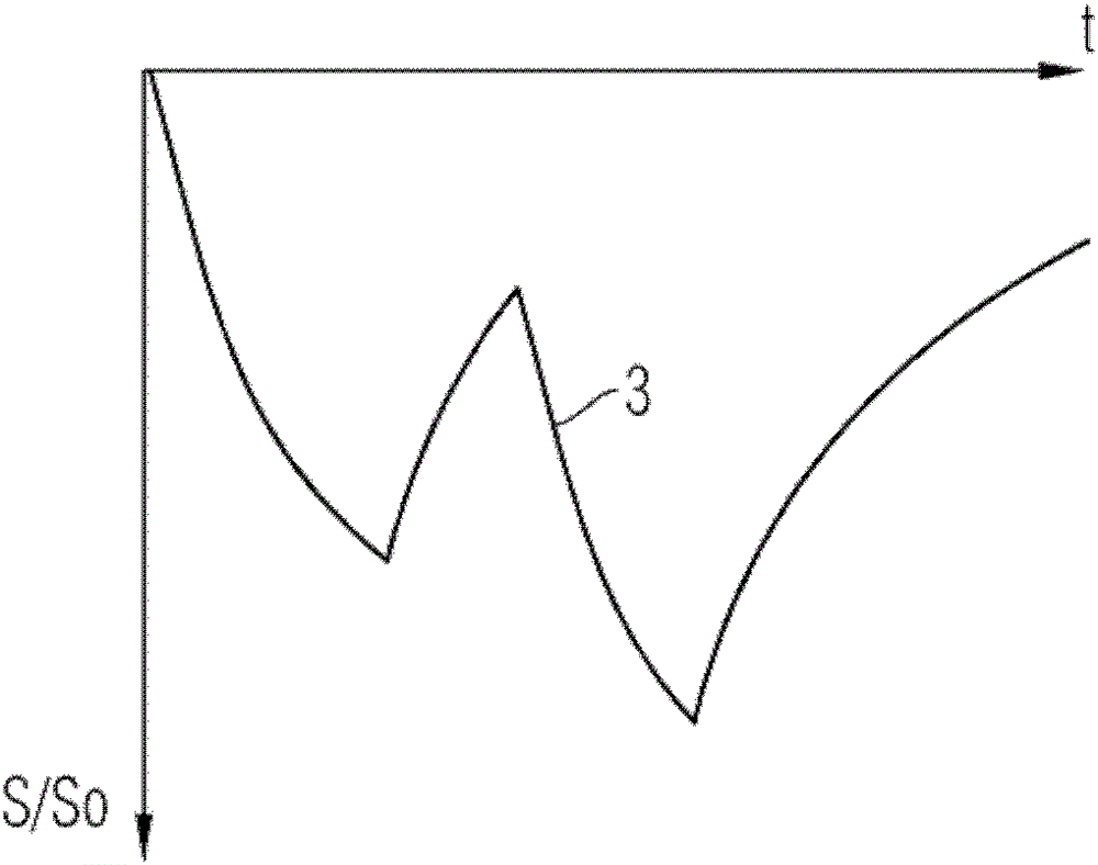
[0042] At this time, irradiation and irradiation intervals are carried out successively, so as to obtain the drift characteristics of the detector, such as image 3 as shown by curve 3 in the Accordingly, the correction factor currently to be applied can be used in each measurement for correcting the measure...


PUM


Abstract

The invention relates to a method for correcting detector data of an X-ray detector (C3, C5), wherein in the current measurement the resulting measurement sensitivity is For the attenuation and the restoration of the attenuation of the measurement sensitivity, the history of the radiation load of the X-ray detector is taken into account and the determined measurement signal is corrected by a correction factor that depends on the radiation load history. The invention also relates to an X-ray imaging system, in particular in a CT system or a C-arm system (C1), having a detector with a plurality of detector elements that are read channel by channel in groups, and a reading device. The reading device has computer aids (C10) for correcting the read detector data before further processing them into projection or tomographic images, wherein the computer aids have a memory in which the program code is stored, said The program code executes the method at runtime.

Description

technical field [0001] The invention relates to a method for correcting detector data of an x-ray detector having a plurality of detector elements and detector element groups, the detector signals of which are transmitted via a channel. [0002] The invention also relates to an x-ray imaging system, in particular in a CT system or a C-arm system, which has a detector with multiple channels which are read out group by channel. a detector element, and a reading device with computer aids for correcting the read detector data before further processing the detector data into projected or tomographic images. Background technique [0003] Solid-state detectors are often used in computed tomography (=CT) and other imaging methods by means of ionizing radiation. It is generally known that extremely high demands are placed on such detectors in CT with regard to sensitivity and linearity, since even small deviations in the reconstructed image can lead to very large artifacts. [0004...

Claims


Application Information

Patent Timeline
Patent Type & Authority Patents(China)
IPC IPC(8): A61B6/02A61B6/03
CPCG01T1/247G01T7/005
Inventor S.卡普勒J.基普斯E.克拉夫特D.尼德尔洛赫纳T.雷切尔C.施罗特T.冯德哈尔
Owner SIEMENS HEALTHCARE GMBH
Learn More