Punching device preventing automobile sealing strip with skeleton from machining deformation

A technology for automobile sealing strips and processing deformation, which is applied in the direction of metal processing, etc., can solve the problems of uneven surface of the incision and deformation of the skeleton, and achieve the effect of preventing the uneven surface of the incision, the deformation of the skeleton, and the deformation of the skeleton.

Active Publication Date: 2012-09-26
瀚德(中国)汽车密封系统有限公司
View PDF6 Cites 6 Cited by
  • Summary
  • Abstract
  • Description
  • Claims
  • Application Information

AI Technical Summary

Problems solved by technology

[0005] The purpose of the present invention is to provide a punching device that can prevent the deformation of the automobile weather strip with skeleto...

Method used


Image

  • Punching device preventing automobile sealing strip with skeleton from machining deformation
  • Punching device preventing automobile sealing strip with skeleton from machining deformation
  • Punching device preventing automobile sealing strip with skeleton from machining deformation

Examples


Embodiment 1

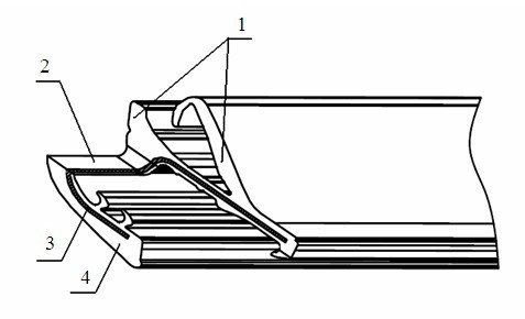
[0063] figure 1 Shown is the sealing strip to be processed in this embodiment. The sealing strip is composed of rubber 4-coated aluminum strip 3, or rubber 4-coated steel strip. It is required that the punched cut includes longitudinal section 1 and transverse section 2. The intersection line formed by the intersection of the longitudinal section 1 and the transverse section 2 and the extending direction of the sealing strip form an inclined angle, which can be 90° or any acute angle; the longitudinal section 1 and the transverse direction The cut planes 2 intersect to form a cut plane angle, which can be any angle in the range of 0 ° ~ 180 ° except 0 ° and 180 °; It is a straight line connection; the longitudinal section 1 and the transverse section 2 are required to have flat surfaces without skeleton deformation.

[0064] figure 2 Shown is the punching device for preventing the processing and deformation of the automobile weather strip with a skeleton according to the pr...

Embodiment 2

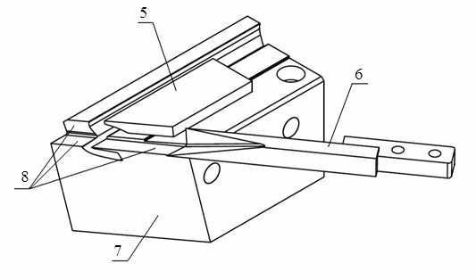
[0072] The punching device for preventing the processing and deformation of the automobile weather strip with skeleton according to the present invention includes a female mold 7, a pressing plate 5 and a cutter 6, and a groove 9 is arranged on the female mold 7 for placing the weather strip, and the The shape of the groove 9 matches the contour shape of the sealing strip to be processed;

[0073] A liftable pressing plate 5 is provided above the female mold 7 for pressing the sealing strip. The pressing plate 5 can move up and down under power drive, and the part of the pressing plate 5 in contact with the surface of the sealing strip is formed as Shape to match the profile of the weatherstrip;

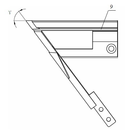
[0074] One end of the female mold 7 is provided with a guiding mechanism 8, which intersects with the groove 9 to form a guiding angle γ, and in this embodiment, the guiding angle γ is set to be 90°;

[0075] There is a sliding fit between the guide mechanism 8 and the cutter 6, whi...


PUM


Abstract

A punching device preventing an automobile sealing strip with a skeleton from machining deformation comprises a female die 7, a pressure plate 5 and a cutter 6, and is characterized in that a groove 9 for placing the sealing strips and a guide mechanism 8 for guiding the cutter 6 to finish the punching operation are arranged on the female die 7; the guide mechanism 8 is intersected with the groove 9 to form a guiding included angle Gamma; the cutter 6 is provided with a horizontal cutting edge 12 and a vertical cutting edge 10; the moving direction of the horizontal cutting edge 12 and the moving direction of the cutter 6 form a cutting edge included angle Beta 1; one end, far from the pressure plate 5, of the horizontal cutting edge 12 inclines towards the punching advance direction of the cutter 6; the cutting edge included angle Beta 1 is smaller than the guiding included angle Gamma; in punching, the sealing strips are cut step by step by the horizontal cutting edge 12 at first, then are cut by the vertical cutting edge 10, so that the impulsive force of the cutter 6 on the sealing strips is reduced, and the deformation of the sealing strips is further reduced, the incision surfaces of the sealing strips are smooth, and the skeleton deformation is avooided.

Description

technical field [0001] The invention relates to a punching device, in particular to a punching device for an automobile sealing strip with a skeleton, and belongs to the technical field of cutting and processing of automobile parts. Background technique [0002] The sealing strip is one of the important components for the sealing of automobile doors and windows, and it is also one of the important decorative parts on the automobile. In the actual production of the sealing strip, it is usually necessary to process a cut at the end of the sealing strip after it is formed, so as to meet the requirements of the assembly connection when the sealing strip is used. Such as figure 1 The sealing strip shown is a commonly used sealing strip for automotive window sealing. According to the requirements of assembly and connection, a cut needs to be processed at one end of the sealing strip, and the cut is required to have a longitudinal section 1 and a transverse section 2. Since part ...

Claims


Application Information

Patent Timeline
IPC IPC(8): B26F1/44
Inventor 张正伟李辉
Owner 瀚德(中国)汽车密封系统有限公司
Why Eureka
Try Eureka