Movable discharging rack

An unloading rack, movable technology, applied in thin material handling, strip winding, transportation and packaging, etc., can solve the problems of inconvenient handling and movement, inability to flexibly combine, and inability to simultaneously discharge materials from multiple racks, etc. To achieve the effect of stable fixation, compact device structure and uniform spacing

Inactive Publication Date: 2015-07-08
ZHEJIANG YUETE TOOL
View PDF6 Cites 0 Cited by
  • Summary
  • Abstract
  • Description
  • Claims
  • Application Information

AI Technical Summary

Problems solved by technology

[0008] Because the existing discharge rack is a cantilever structure, and the center of gravity of the raw materials is shifted out of the discharge rack, the base must be large enough, or fixed on the ground to ensure that the discharge rack does not fall down, and it is inconvenient to carry and move, and cannot be flexibly combined ( That is, multiple material racks cannot be discharged at the same time), and the movable sleeve needs to be adjusted for materials with different inner diameters

Method used


Image

  • Movable discharging rack
  • Movable discharging rack
  • Movable discharging rack

Examples


Embodiment Construction

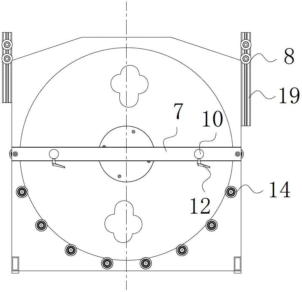
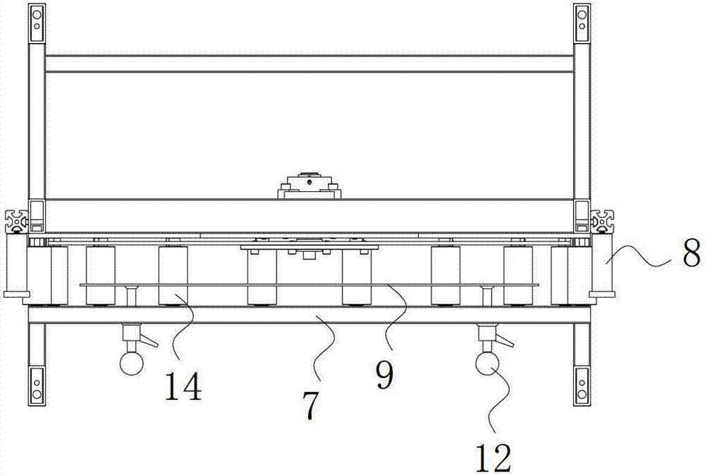
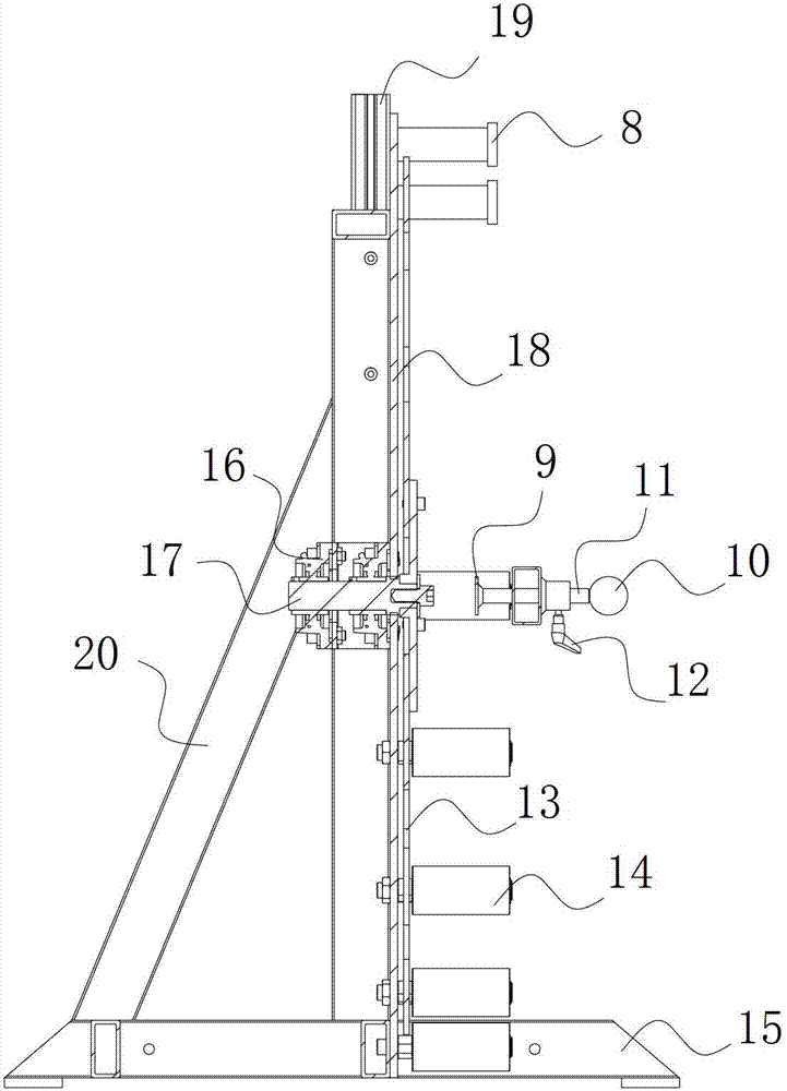
[0037] Such as figure 1 , figure 2 , image 3 As shown, the movable discharge rack of the present invention includes a support frame 15 , a material tray 13 rotatably connected to the support frame 15 , a material blocking device installed on the support frame 15 and a raw material support wheel 14 pivotally connected to the support frame 15 .

[0038] The support frame 15 includes a base and a wallboard 18 standing on the base. The vertical wallboard 18 is fixed with a bearing 16. The bearing 16 is passed through a feeder shaft 17 that rotates with it, and the feeder 13 is fixed on the feeder shaft 17. At one end, the material tray 13 can rotate freely relative to the wallboard 18. The raw material is placed between the material tray 13 and the material blocking device, and the raw material is coiled into a disk shape. When discharging, the freely rotatable material tray 13 can reduce its contact with The friction between raw materials is beneficial to the discharge.

[0...


PUM


Abstract

The invention discloses a movable discharging rack. The movable discharging rack comprises a supporting frame, a tray which is in rotatable connection with the supporting frame and is perpendicularly arranged, a material blocking device which is arranged on the supporting frame, and at least three raw material supporting wheels which are coupled on the supporting frame, wherein a gap between the material blocking device and the tray is a raw material placing area, and the raw material supporting wheels are arranged in an arc shape below the raw material placing area. The movable discharging rack changes a cantilever structure in the prior art, is compact in structure, is convenient to move, can realize unintentional discharging, and can adjust the discharging height.

Description

technical field [0001] The invention relates to a discharge device for wrapping a band saw blade, in particular to a movable discharge rack. Background technique [0002] Tungsten carbide band saw blade is a saw blade with cemented carbide as the tip material welded to the back material of the saw blade. Tungsten carbide has good wear resistance, the saw teeth are not easy to deform and dull, and have a long service life. [0003] The utility model with the application number 00208563.1 discloses a cemented carbide band saw blade, which is mainly composed of a saw band body and cemented carbide saw teeth. The saw band body is ring-shaped, and cemented carbide saw teeth are welded on it; The sawtooth is wide at the end of the sawtooth and narrow at the root, and a set of two teeth cuts a saw path. This kind of saw blade is used for sawing copper, aluminum non-ferrous metals, hard wood, plastic, fiberglass and other materials, and solves the problem of short service life of b...

Claims


Application Information

Patent Timeline
Patent Type & Authority Patents(China)
IPC IPC(8): B65H16/02
Inventor 陶狄锋顾军林严岳峰高同尧丁杰锋刘曾炜盛要军石利娟
Owner ZHEJIANG YUETE TOOL
Why Eureka
Try Eureka