Yarn tension device

A technology for yarn tension and tension adjustment, which is applied in the directions of transportation and packaging, transportation of filamentous materials, and thin material handling, etc. Good lateral stability, good for unwinding and stable tension

Inactive Publication Date: 2012-09-26
JIANGSU WANGONG TECH GRP CO LTD
View PDF6 Cites 11 Cited by
  • Summary
  • Abstract
  • Description
  • Claims
  • Application Information

AI Technical Summary

Problems solved by technology

[0002] At present, there is a lack of a limited tension device in the tension system of the side yarn package yarn winding of the shuttlel

Method used


Image

  • Yarn tension device
  • Yarn tension device

Examples


Embodiment Construction

[0017] The present invention will be described in detail below with reference to the accompanying drawings and in combination with embodiments.

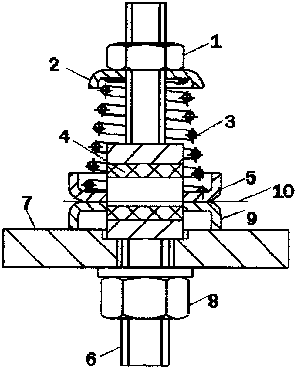
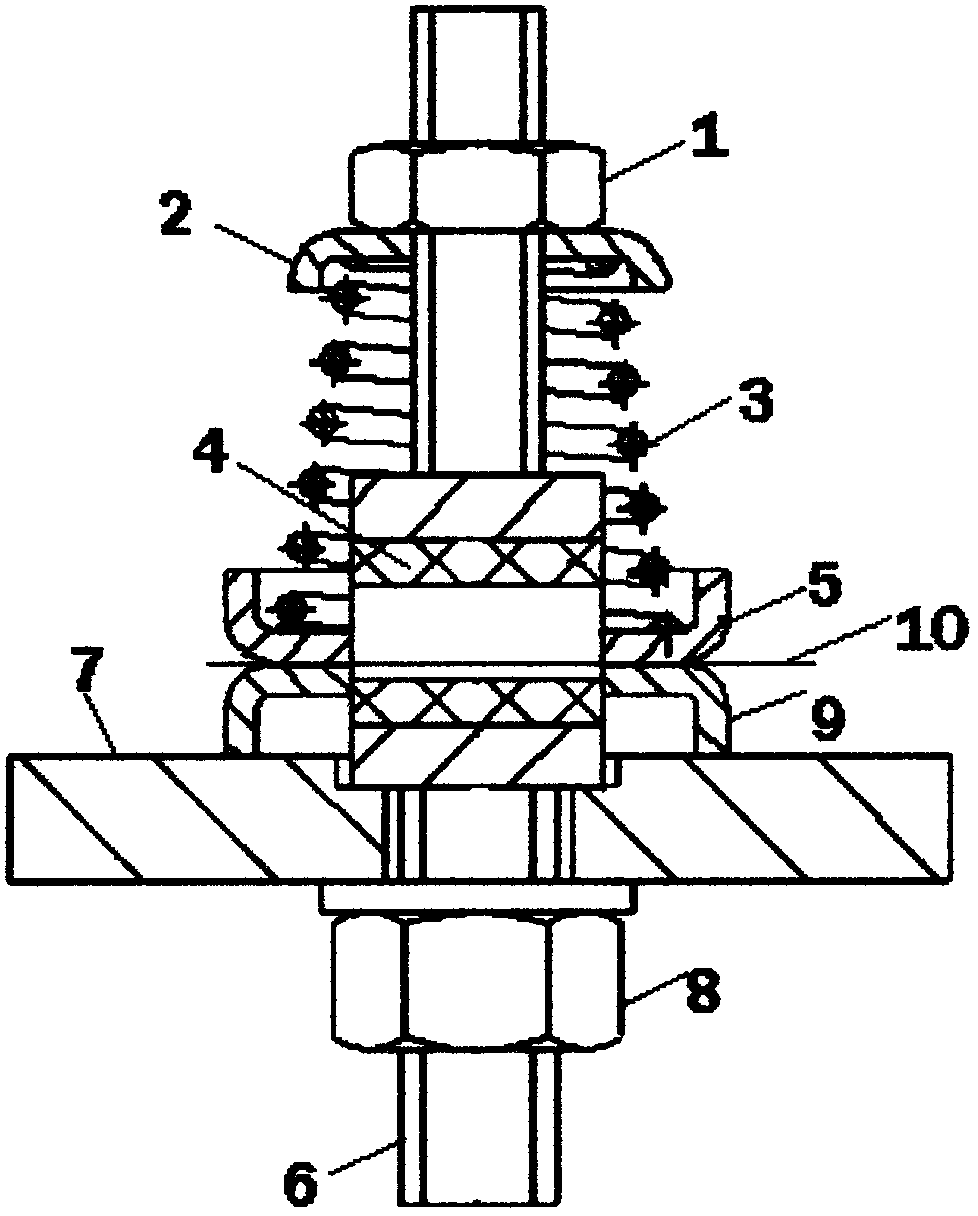
[0018] see figure 1 As shown, a yarn tension device includes a support plate 7, and a shaft hole is provided on the support plate 7, and a tension adjustment shaft 6 with a "middle" structure is arranged in the shaft hole, and the tension adjustment shaft The inner hole of 6 is fixed with a hole porcelain column 4 by glue, the lower end of the tension adjustment shaft 6 is fixed on the support plate 7 by the second nut 8, and the upper end of the tension adjustment shaft 6 is screwed with the first nut 1. A conical coil spring 3 is arranged under the first nut 1, the conical coil spring 3 is sleeved on the tension adjustment shaft 6, and the lower end of the conical coil spring 3 is provided with a lower positioning plate 5 , a fixed disk 9 is arranged below the lower positioning disk 5, the fixed disk 9 is fixed on the support plat...


PUM


Abstract

The invention discloses a yarn tension device, comprising a supporting plate, wherein a shaft hole is arranged on the supporting plate, and a tension adjusting shaft with a structure shaped like a Chinese character 'zhong' is arranged in the shaft hole; a perforated ceramic column is fixed in an inner hole of the tension adjusting shaft by glue, and the lower end of the tension adjusting shaft is fixedly arranged on the supporting plate through a second nut; the upper end of the tension adjusting shaft is provided with a first nut, and a conical spiral spring is arranged below the first nut and is sleeved on the tension adjusting shaft; the upper end of the conical spiral spring is provided with an upper positioning disc, and the lower end of the conical spiral spring is provided with a lower positioning disc; and a first fixing disc is arranged below the lower positioning disc and is fixedly arranged on the supporting plate, and a yarn penetrates through the hole of the perforated ceramic column and is clamped between the two planes of the lower positioning disc and the fixing disc. According to the yarn tension device provided by the invention, a selvedge bobbin yarn has more stable tension in winding, and the unwinding of the yarn is favorable.

Description

technical field [0001] The invention belongs to the field of looms, and in particular relates to a yarn tension device, which is used for controlling the winding tension of side yarn bobbins of shuttleless looms. Background technique [0002] At present, there is a lack of a limited tension device in the winding tension system of the side yarn cheese of the shuttleless loom, which leads to unstable tension of the side yarn cheese during winding, which is not conducive to the unwinding of the yarn. Contents of the invention [0003] In order to overcome the deficiencies in the prior art, the object of the present invention is to provide a yarn tension device, which can ensure that the side yarn cheese has a relatively stable tension when winding, which is beneficial to the yarn tension. Unwind. [0004] In order to achieve the above-mentioned technical purpose and achieve the above-mentioned technical effect, the present invention is realized through the following technica...

Claims


Application Information

Patent Timeline
IPC IPC(8): B65H59/10B65H57/06
Inventor 周平郑志刚
Owner JIANGSU WANGONG TECH GRP CO LTD
Why Eureka
Try Eureka