
Charged internal combustion engine and method to operate such an engine

一种内燃发动机、增压器的技术,应用在内燃活塞发动机、燃烧发动机、发动机元件等方向

Inactive Publication Date: 2012-09-26
FORD GLOBAL TECH LLC
View PDF5 Cites 5 Cited by
  • Summary
  • Abstract
  • Description
  • Claims
  • Application Information

AI Technical Summary

Problems solved by technology

[0013] The inventors have recognized the problems with the above-described approaches and provide herein a system that at least partially addresses them

Method used


Image

  • Charged internal combustion engine and method to operate such an engine
  • Charged internal combustion engine and method to operate such an engine
  • Charged internal combustion engine and method to operate such an engine

Examples


Embodiment Construction

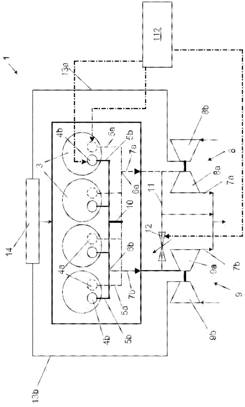
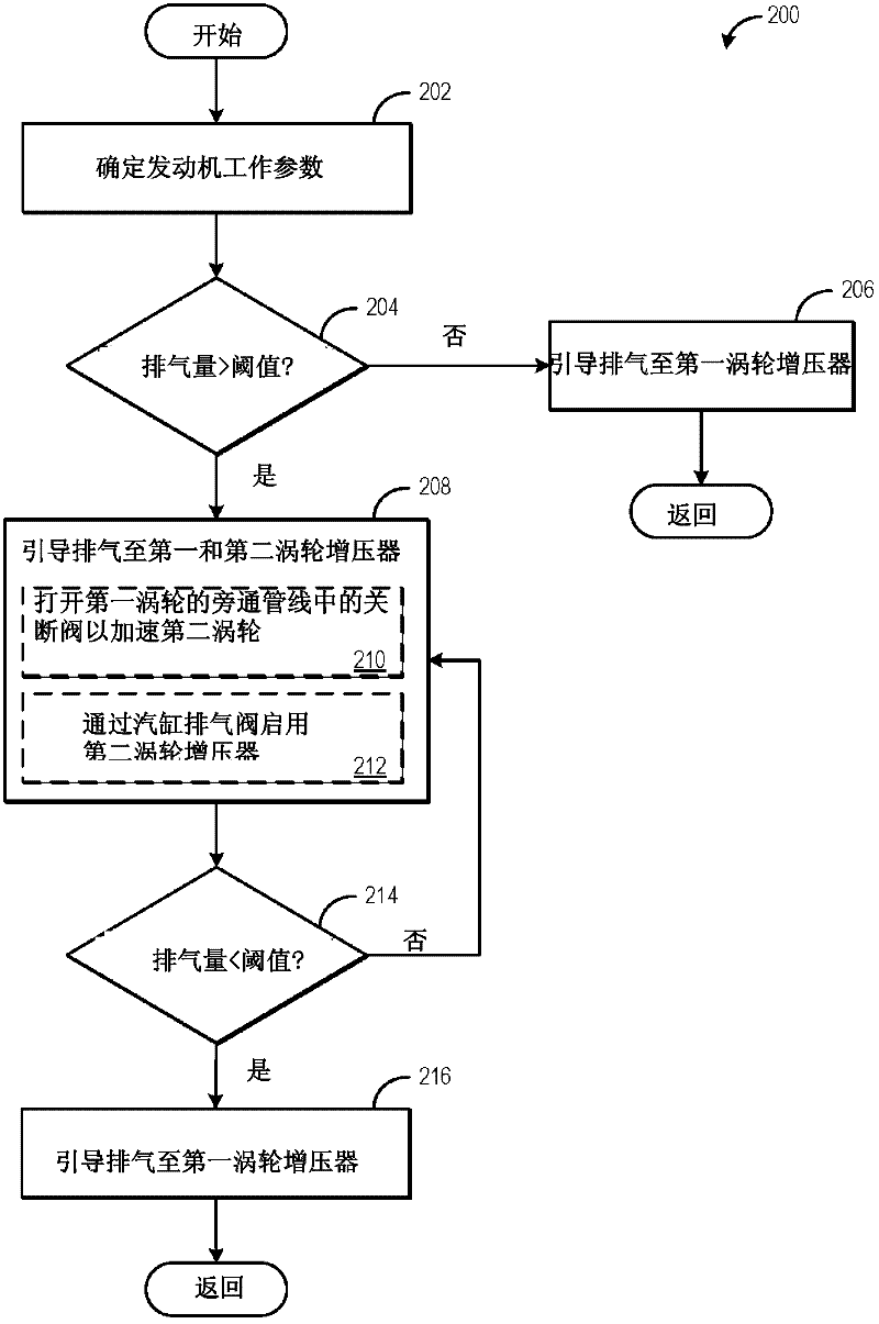
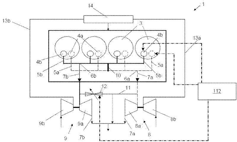
[0030] Embodiments are provided that direct exhaust gas through a plurality of exhaust manifolds each connected to a turbocharger. figure 1 is an engine schematic diagram illustrating an example embodiment of an internal combustion engine according to the disclosure. figure 2 is a flowchart illustrating one example method that may be performed by the engine of the present disclosure.

[0031]In the context of the present disclosure, the term "internal combustion engine" includes in particular spark ignition engines, but also diesel engines and hybrid internal combustion engines.

[0032] figure 1 An embodiment of an internal combustion engine 1 is shown schematically, which is equipped with two exhaust-gas turbochargers 8 , 9 . Each exhaust-gas turbocharger 8, 9 comprises a turbine 8a, 9a and a compressor 8b, 9b. The hot exhaust gases are expanded in the turbines 8a, 9a releasing energy, and the compressors 8a, 9a compress the charge fed to the cylinder 3 via the intake li...


PUM


Abstract

A supercharged internal combustion engine having at least two exhaust-gas turbochargers is provided. The engine includes a first exhaust manifold and a second exhaust manifold which are permanently connected to one another upstream of the two turbines of the turbochargers via at least one connecting duct which cannot be closed off. In this way, overflow of exhaust from the one exhaust manifold may be transferred to the other exhaust manifold.

Description

[0001] related application [0002] This application claims priority from European Patent Application No. 11159786.0 filed on March 25, 2011, the entire content of which is hereby incorporated by reference for all purposes. technical field [0003] The present disclosure relates to a supercharged internal combustion engine having at least two exhaust-gas turbochargers. Background technique [0004] An internal combustion engine has a cylinder block and at least one cylinder head interconnected to form cylinders. In order to control the charge exchange, an internal combustion engine requires control elements, usually in the form of valves, and actuating means for activating said control elements. The valve actuation mechanism required for valve movement (including the valve itself) is referred to as the valve actuation. A cylinder head is typically used to house the valve drive mechanism. [0005] During charge exchange, the combustion gases are expelled via the cylinder o...

Claims


Application Information

Patent Timeline
Patent Type & Authority Applications(China)
IPC IPC(8): F02B37/007F02B37/18F01N13/10
CPCF01L1/26F02B37/02F02F1/243F01L1/34F02B37/007Y02T10/144F01L13/00F02B37/025F02B37/18F01N13/107Y02T10/18F02D13/0257F02D23/02F01L13/0005Y02T10/12
Inventor N·A·斯科恩R·弗莱德菲尔特G·巴奇K·S·库巴赫
Owner FORD GLOBAL TECH LLC
Learn More