Electric iron

A technology for electric irons and irons, applied to hand irons, washing devices, textiles and papermaking, etc., can solve problems such as no improvement, and achieve the effects of preventing burnout, reducing leakage, and preventing local overheating

Inactive Publication Date: 2011-08-10
BSH BOSCH & SIEMENS HAUSGERAETE GMBH
View PDF10 Cites 0 Cited by
  • Summary
  • Abstract
  • Description
  • Claims
  • Application Information

AI Technical Summary

Problems solved by technology

However, this has the disadvantage that separate thermal bridges that increase the heat flow from the heating body to the contact point lead to only negligible or no improvement if the contact point is already arranged directly on the heating body

Method used


Image

  • Electric iron
  • Electric iron
  • Electric iron

Examples


Embodiment Construction

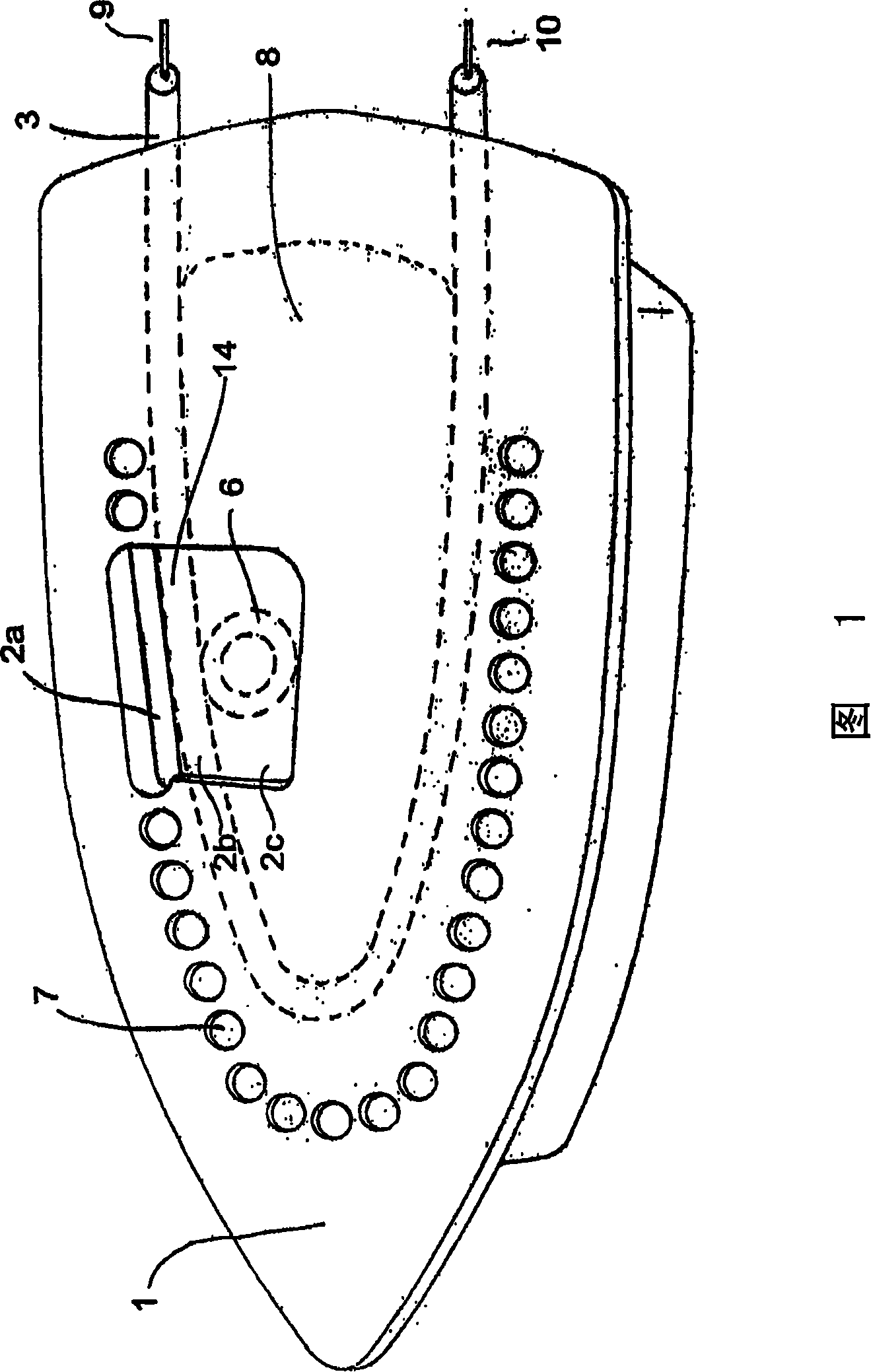
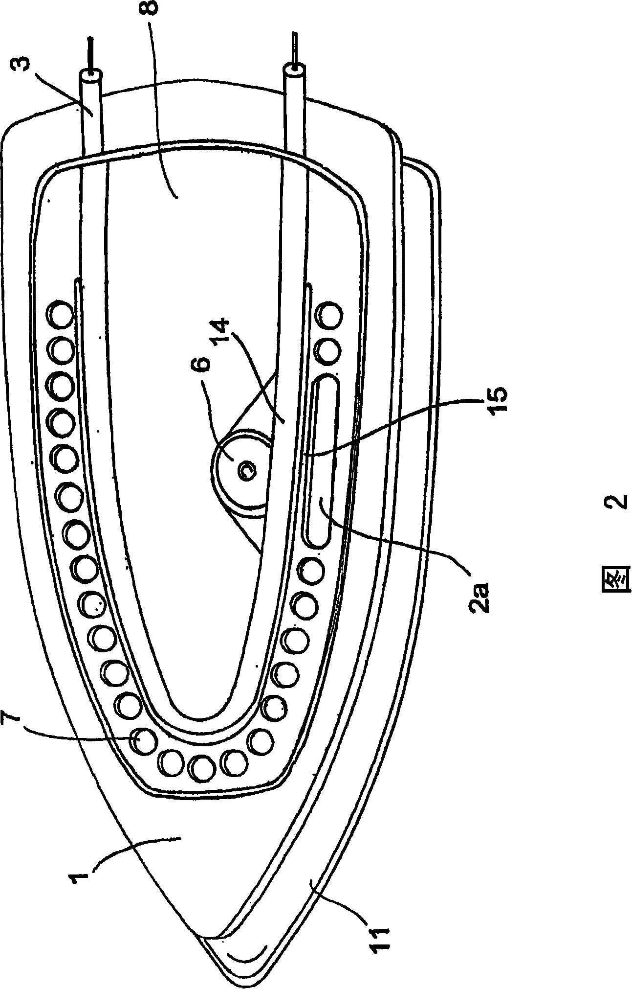
[0029] figure 1 It shows the bottom edge of the iron soleplate 1 proposed by the present invention, and a resistance heating body 3 is formed in the iron soleplate 1 manufactured by the aluminum die-casting method. The heating body 3 is U-shaped and extends along the steam escape holes 7 which connect a steam chamber 8 with the bottom edge of the iron soleplate 1. The ends 9 and 10 of the two legs of the U-shaped heating body 3 protrude from the steam chamber 8 and have electrical contacts.

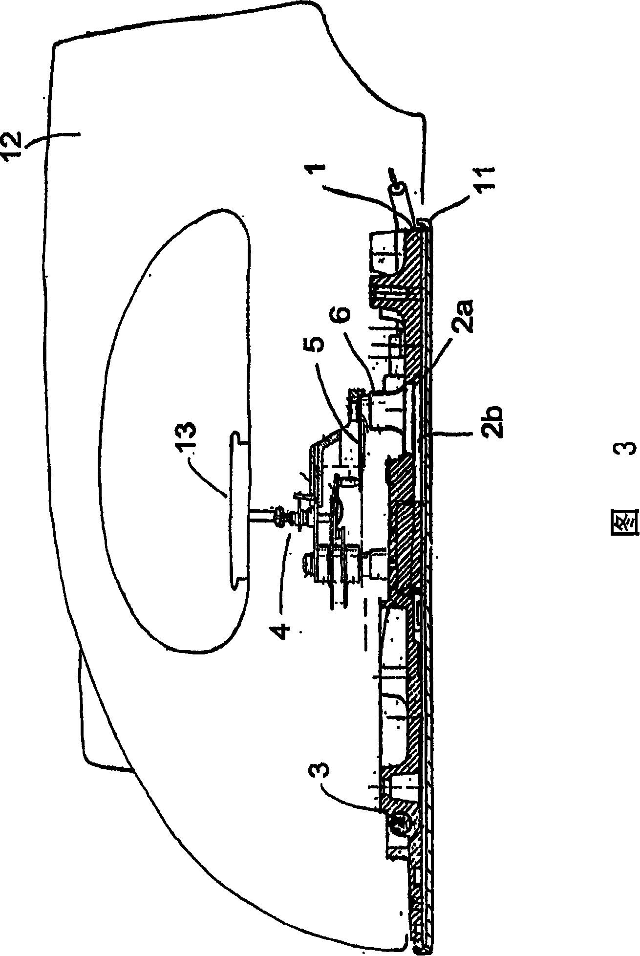
[0030] Below the steam chamber 8, a dome-shaped contact point 6 is cast on the soleplate 1 of the iron. The contact point 6 forms a tube seat, and the temperature probe 5 of a regulating device 4 contacts the tube seat. The dome-shaped contact point 6 directly adjoins the heating body section 14 of one leg of the U-shaped heating body 3. The dome-shaped contact point 6 is raised on the upper edge of the soleplate 1 of the iron. Below the dome-shaped contact point 6, there is a gap space 2...


PUM


Abstract

The invention relates to an electric iron which comprises an iron sole (1) heated by a heating element (3) and a control device (4) for controlling said heating element (3). Said control device comprises a temperature sensor (5) that is thermally linked with the soleplate (1) at a point of contact (6). In order to improve the thermal coupling of the point of contact to the heating element, the iron sole (1) is provided with a gap (2) that is locally defined in the area of the point of contact (6) and a pertaining heating element section (14) and that at least reduces heat conduction of the flow of heat emitted by the heating element (3) in a direction away from the point of contact (6). The heat on the iron sole (1) can thus be better controlled even if the point of contact (6) is located either directly on or at least very close to the heating element (3), wherein the iron sole (1) is covered by a soleplate (11), and the point of contact (6) is arranged eccentrically in relation to the axis of symmetry of the heating element (3) in the vicinity of one of the two legs of the heating element (3), then the at least one separated opening (2a) on the iron sole (1) can extend along the outer edge of this leg in the region of the point of contact (6). This invention has the advantage that if the point of contact (6) is directly arranged on the heating element (3) or at least near the heating element (3), the heat regulation on the iron sole (1) can be improved.

Description

Technical field [0001] The invention relates to an electric iron. The electric iron is provided with a soleplate heated by a heating body and an adjusting device for adjusting the heating body. The adjusting device includes a temperature probe which is thermally connected with the soleplate of the iron at a contact point. Background technique [0002] Electric irons of this type have been disclosed in DE 42 12 286 A1. The electric iron includes a metal soleplate and a U-shaped resistance heating body. The heating body is embedded in the iron soleplate manufactured by the die-casting method in a rigid joint according to the shape. When the iron is working, the heating body is supplied with electric energy through the electrical contact on the ends of the two legs of the U-shaped heating body. The heating body provides the input electric energy to the soleplate of the iron in the form of heat. In order to adjust the temperature of the soleplate of the iron, a thermostat is prov...

Claims


Application Information

Patent Timeline
Patent Type & Authority Patents(China)
IPC IPC(8): D06F75/38
CPCD06F75/38D06F75/24
Inventor C·阿尔万多斯鲁伊斯德奥A·弗朗柯弗
Owner BSH BOSCH & SIEMENS HAUSGERAETE GMBH
Why Eureka
Try Eureka