
Concrete crack detector with reinforcing bar as electrode

A crack detector and concrete technology, applied in the direction of material impedance, etc., can solve problems such as the incompatibility of concrete, and achieve the effects of avoiding catastrophic damage, convenient construction and long service life

Inactive Publication Date: 2012-09-26
SICHUAN UNIV
View PDF6 Cites 23 Cited by
  • Summary
  • Abstract
  • Description
  • Claims
  • Application Information

AI Technical Summary

Problems solved by technology

China Patent No. 200610020932.8 "Concrete Damage Detection Method and Equipment Based on Impedance Imaging" provides a concrete damage detection method and equipment. This method uses impedance imaging technology to obtain the health status of concrete. The detection electrode, the embedded detection electrode is not well compatible with the concrete, and the construction process and construction method have been changed, so there are certain application limitations

Method used


Image

  • Concrete crack detector with reinforcing bar as electrode
  • Concrete crack detector with reinforcing bar as electrode
  • Concrete crack detector with reinforcing bar as electrode

Examples


Embodiment 1

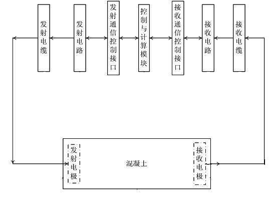
[0036] The detector is composed of a transmitting electrode, a transmitting cable, a transmitting circuit, a transmitting communication control interface, a control and calculation module, a receiving communication control interface, a receiving circuit, a receiving cable, and a receiving electrode. The transmitting electrode is connected to the transmitting circuit through the transmitting cable, the signal of the transmitting circuit is sent by the transmitting electrode, the receiving electrode is connected to the receiving circuit through the receiving cable, and the receiving circuit amplifies and filters the signal received by the receiving electrode. The transmitting circuit is connected to the control and calculation module through the transmission communication control interface, and the two-way communication control between the control and calculation module and the transmitting circuit. The receiving circuit is connected to the control and calculation module through ...

Embodiment 2

[0050] Both the transmitting electrode and the receiving electrode are ring electrodes, and the electrodes are buried in the concrete when the concrete is poured. The transmitting cable is connected to B1 and B2 of the transmitting electrode, and the receiving cable is connected to B1 and B2 of the receiving electrode. The analog signal output by the waveform generator of the transmitting circuit is directly output to the control and computing module through the transmitting communication and control interface. The single-chip microcomputer of the receiving circuit is connected to the amplification and filtering circuit through the IO pin, and the analog signal is directly transmitted to the control and calculation module after controlling the amplification and filtering circuit through the IO pin. The communication interface of the transmitting circuit and the receiving circuit adopts a parallel communication interface. The microprocessor chip contained in the control and ca...

Embodiment 3

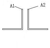
[0052] The transmitting electrode adopts dual-type reinforced electrode, and the receiving electrode adopts annular reinforced electrode. The electrodes are buried in the concrete when the concrete is poured. The transmitting cable is connected to A1 and A2 of the transmitting electrode, and the receiving cable is connected to B1 and B2 of the receiving electrode.


PUM


Abstract

The invention discloses a concrete crack detector with a reinforcing bar as an electrode. A reinforcing bar emission electrode and a reinforcing bar receiving electrode are embedded in concrete, wherein the emission electrode is connected with an emission circuit through an emission cable; a signal transmitted by the emission circuit is sent out from the concrete through the emission electrode; the receiving electrode is connected with a receiving circuit through a receiving cable; and the receiving circuit is used for amplifying and filtering a signal received by the receiving electrode. An output signal of the emission circuit is connected to a control and computation module through an emission communication control interface, and two-way communication control is performed between the control and computation module and the emission circuit. An output signal of the receiving circuit is connected to the control and computation module through a receiving communication control interface, and two-way communication control is performed between the control and computation module and the receiving circuit. As the reinforcing bar is used as the electrode, the original construction features and stress features of the concrete do not change, a construction process and a construction method have no need to change, and the electrode and the concrete structure have the same service life. The concrete crack detector with the reinforcing bar as the electrode has the advantages of simplicity in design, convenience for construction, low cost and long service life.

Description

technical field [0001] The invention belongs to the category of building material detection and relates to concrete quality monitoring. Background technique [0002] Concrete is an important engineering material widely used in housing construction, bridge engineering, water conservancy engineering, etc., but the occurrence of concrete cracks is often unavoidable. The occurrence and development of cracks will seriously damage the integrity of the structure and directly endanger the safety of engineering structures. Therefore, crack detection is an important content of engineering safety monitoring. Regular or real-time crack detection is required for highways, bridges, dams and other industrial and civil buildings. However, the prediction and prediction of concrete structure cracks, the diagnosis and monitoring of concrete cracks are one of the main problems that need to be solved urgently in the world today. China Patent No. 200610020932.8 "Concrete Damage Detection Method...

Claims


Application Information

Patent Timeline
Patent Type & Authority Applications(China)
IPC IPC(8): G01N27/02
Inventor 莫思特李碧雄
Owner SICHUAN UNIV
Learn More