A Defect Region Extraction Method

A region extraction and defect technology, applied in image data processing, instruments, calculations, etc., can solve the problems of slow extraction method and unsuitable real-time detection, and achieve the effect of fast speed and improved detection speed

Inactive Publication Date: 2015-10-28
HENAN UNIV OF SCI & TECH
View PDF4 Cites 0 Cited by
  • Summary
  • Abstract
  • Description
  • Claims
  • Application Information

AI Technical Summary

Problems solved by technology

[0003] The purpose of the present invention is to provide a defect area extraction method to solve the problem that the existing extraction method is slow and unsuitable for real-time detection

Method used


Image

  • A Defect Region Extraction Method
  • A Defect Region Extraction Method

Examples


Embodiment Construction

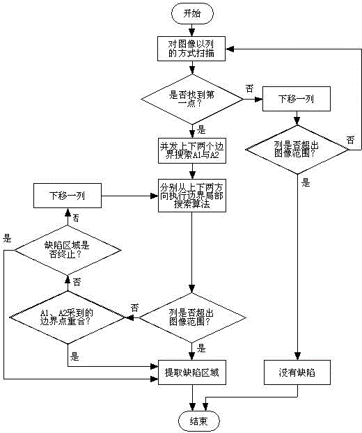
[0013] The defect area extraction method is as follows figure 1 , 2 As shown, the specific steps are as follows:

[0014] (1) Scan the image column by column in a column mode;

[0015] (2) During the scanning process, if the image gray value difference of a point is found to be greater than the preset threshold, the point is a suspicious defect point;

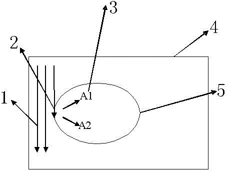
[0016] (3) Extend along the scanning direction, execute the boundary local search algorithm from the upper and lower directions respectively to find the upper and lower defect boundaries A1 and A2;

[0017] (4) Until the boundary points of the upper and lower boundaries coincide, extract the defect area.

[0018] The boundary local search algorithm in step (3) is an existing technology, and you can refer to Wu Guifang's "Boundary Local Search Algorithm and Application" published in February 2005, Volume 25, Issue 2.

[0019] figure 2 In 1 indicates that the sequential scanning direction is column scanning, 2 indicates the first susp...


PUM


Abstract

The invention relates to a defect region extraction method which comprises the following steps: firstly, carrying out line or row gradual scanning on an image; in the process of scanning, if finding that the image grey-level difference of a point is greater than a preset threshold value, determining that the point is a suspicious defect point; carrying out expanding along the scanning direction, and respectively executing a boundary local-search algorithm from the up-and-down direction or the left-and-right direction so as to find out two defect boundaries in the up-and-down direction and the left-and-right direction; and until the boundary points acquired from the up-and-down or left-and-right boundary are coincided, extracting a defect region. According to the method, in the process of extracting a defect, an image is only subjected to scanning operation for one time, and after a first point of the defect is detected, the scanning process is simpler, and detection can be performed automatically tightly along the defect region until the defect region is completely extracted; and the detecting method is rapid in speed, and applicable to the defect region extraction with high requirements on rapid edge-region positioning and instantaneity.

Description

Technical field [0001] The invention belongs to the technical field of surface defect quality detection, and relates to a defect area extraction method. Background technique [0002] At present, in the surface defect quality inspection technology, the image is generally processed, the defect area is first extracted, and then the feature extraction is performed on the defect area to identify and classify the defect. For the first stage of defect area extraction, the traditional defect area extraction method mainly performs various filtering on the image, and then binarizes the filtered image to obtain the defect area. For example, the X-ray image defect extraction method based on sub-regional adaptive median filtering is to perform one-dimensional median filtering based on scan lines in different directions according to the characteristics of grayscale changes in different regions of the image, and make the length of the filter follow the defect. The size is automatically adjuste...

Claims


Application Information

Patent Timeline
Patent Type & Authority Patents(China)
IPC IPC(8): G06T7/00
Inventor 吴贵芳
Owner HENAN UNIV OF SCI & TECH
Why Eureka
Try Eureka