Digital adjustable resistor and adjusting method thereof

A technology for adjusting resistance and resistance, which is applied in the direction of adjustable resistors, resistors, resistance elements including multiple resistance elements, etc., can solve problems such as insufficient precision and inability to achieve high-precision adjustment of resistance, and achieve the effect of adjustment

Active Publication Date: 2012-09-26
ZHEJIANG JUEXIN MICROELECTRONICS CO LTD
View PDF5 Cites 22 Cited by
  • Summary
  • Abstract
  • Description
  • Claims
  • Application Information

AI Technical Summary

Problems solved by technology

[0004] Although a large resistor can be converted into a small resistor by connecting multiple resistors in parallel with multiple resistors connected in series with

Method used


Image

  • Digital adjustable resistor and adjusting method thereof
  • Digital adjustable resistor and adjusting method thereof
  • Digital adjustable resistor and adjusting method thereof

Examples


Embodiment 1

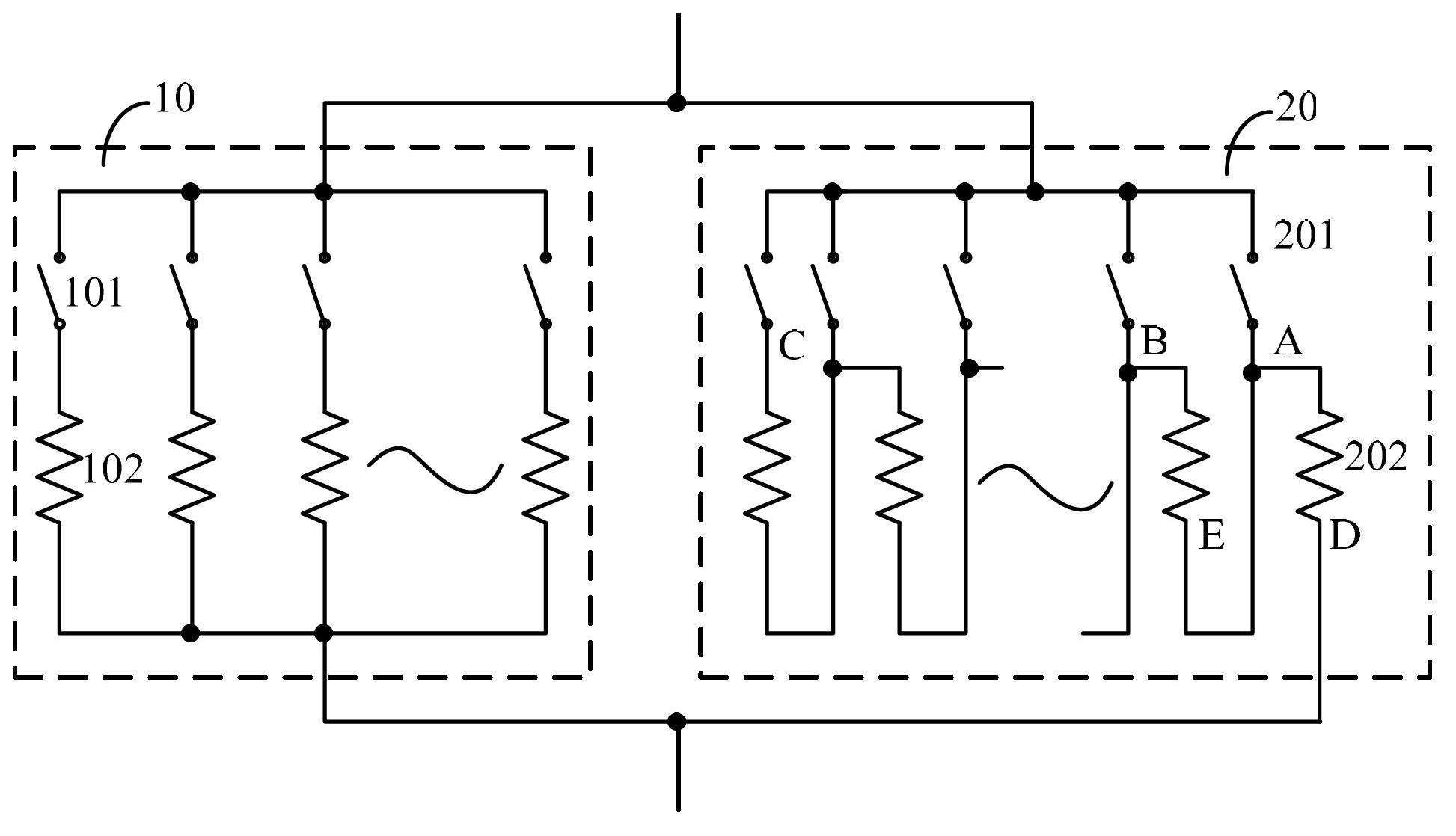
[0035] figure 2 A schematic diagram of Embodiment 1 of the digitally adjustable resistor of the present invention is shown. refer to figure 2 , the digitally adjustable resistor includes: a controlled resistor string 10 and an adjusted resistor string 20 . The controlled resistor string 10 is connected in parallel with the adjusted resistor string 20 .

[0036] Wherein, the controlled resistor string 10 obtains an approximate value of the required resistance value by adjusting the number of first resistors 102 connected in parallel. The adjusting resistor string 20 is connected in parallel with the controlled resistor string 10 , and is used to adjust the resistance value of the digitally adjustable resistor by adjusting the number of the second resistors 202 connected in series to obtain a desired resistance value.

[0037] Specifically, in this embodiment, the controlled resistor string 10 adjusts the number of first resistors 102 connected in parallel through a plurali...

Embodiment 2

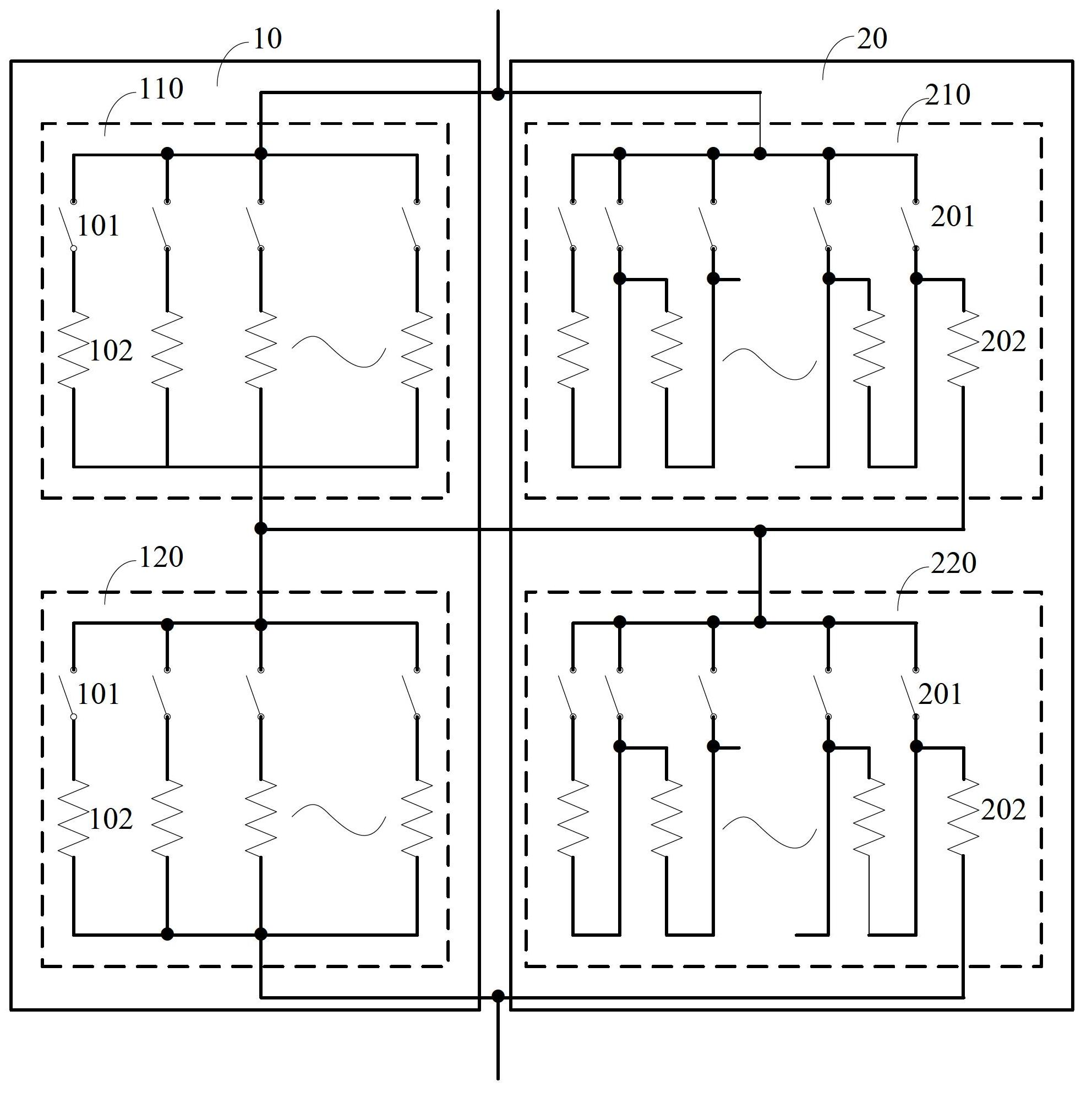
[0058] image 3 A schematic diagram of Embodiment 2 of the digitally adjustable resistor of the present invention is shown. refer to image 3 , the digitally adjustable resistor includes: a controlled resistor string 10 and an adjusted resistor string 20 . The controlled resistor string 10 is connected in parallel with the adjusted resistor string 20 .

[0059] Compared with Embodiment 1, the difference of this embodiment is that: the controlled resistor string 10 includes a first sub-controlled resistor string 110 and a second sub-controlled resistor string 120 connected in series. The adjusting resistor string 20 includes a first sub-adjusting resistor string 210 and a second sub-adjusting resistor string 220 connected in series. Moreover, the first sub-controlled resistor string 110 is connected in parallel with the first sub-regulated resistor string 210; the second sub-controlled resistor string 120 is connected in parallel with the second sub-regulated resistor string...


PUM


Abstract

Disclosed are a digital adjustable resistor and an adjusting method thereof. The digital adjustable resistor comprises a controlled resistor string and an adjustable resistor string which are connected in parallel, an approximate value of required resistance can be obtained via the controlled resistance string by means of adjusting the quantity of first resistors connected in parallel, the adjustable resistor string is connected with the controlled resistor string, the resistance of the digital adjustable resistor is adjusted by means of adjusting the quantity of second resistors connected in serial, and accordingly the required resistance is obtained. The adjusting method includes connecting a plurality of first resistors in parallel to obtain the approximate value of the required resistance; connecting a plurality of second resistors in series according to the required resistance and the approximate value of the required resistance so that the resistance of the digital adjustable resistor is adjusted; and connecting the first parallelly-connected resistors with the second serially-connected resistors in parallel to obtain the required resistance. The digital adjustable resistor and the adjusting method for the digital adjustable resistor have the advantage that small-step and high-precision adjustment of the resistor is realized.

Description

technical field [0001] The invention relates to the technical field of electronic circuits, in particular to a digital adjustable resistor and an adjusting method thereof. Background technique [0002] Many circuits require well-matched resistors, however, the available matches are often limited due to process constraints. Circuits that require good matching include, but are not limited to, analog-to-digital converters (ADCs) and digital-to-analog converters (DACs). [0003] In order to obtain a resistor with a smaller resistance value in the circuit, the resistance value of the resistor is usually adjusted by connecting the resistors in parallel. In the Chinese patent with publication number CN101275876A, a method for designing bridge arm balance compensation resistors is disclosed. figure 1 A schematic diagram showing a variable bridge arm balance compensation resistor in the prior art, refer to figure 1 , the variable bridge arm balance compensation resistor 50 is a va...

Claims


Application Information

Patent Timeline
IPC IPC(8): H01C10/16H01C10/50
Inventor 白建军张镭周桂华陈瑞欣
Owner ZHEJIANG JUEXIN MICROELECTRONICS CO LTD
Why Eureka
Try Eureka