
High-performance omnidirectional antenna

An omnidirectional antenna, high-performance technology, applied in the direction of antenna support/installation device, radiating element structure, etc., can solve the problems of large antenna volume, low gain, high cost, etc., and achieve simple antenna structure, small change in pitch angle, Use the effect of high performance

Inactive Publication Date: 2012-09-26
TAIXING XUNDA COMM EQUIP
View PDF4 Cites 1 Cited by
  • Summary
  • Abstract
  • Description
  • Claims
  • Application Information

AI Technical Summary

Problems solved by technology

The bandwidth of the series-fed antenna is narrow, the high-frequency and low-frequency lobes of the antenna do not have the same upturn or downtilt angle, the gain is low, and the sidelobes are large, which affects the coverage; the installation of the center-fed antenna is not very convenient
The feeding cable routing of conventional parallel-fed antennas is cumbersome, and sometimes it is even necessary to place the feeding cable outside the half-wave oscillator of the unit, which affects the radiation pattern of the antenna; it also requires additional balanced and unbalanced conversion devices to cause antenna Excessive volume, poor out of roundness, complex production, poor consistency, high cost

Method used


Image

  • High-performance omnidirectional antenna
  • High-performance omnidirectional antenna
  • High-performance omnidirectional antenna

Examples


Embodiment Construction

[0013] The present invention will be further described below in conjunction with drawings and embodiments.

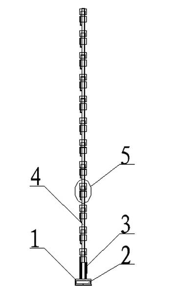
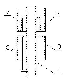
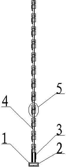
[0014] figure 1 , 2 As shown, a high-performance omnidirectional antenna includes a fixed base 1, a power divider 2, a nylon rod 3, a metal support rod 4 and 12 radiating units 5, and the 12 radiating units 5 are equidistantly connected in series with the metal supporting rod 4, The metal support rod 4 is supported on the fixed base 1, and the fixed base 1 is provided with a power distributor 2; the radiation unit 3 includes two metal drums with the same diameter, the opening of the upper metal drum 6 faces upward, and the upper metal drum 6 The bottom of the bucket is recessed upwards to form an inner drum 7 with a diameter smaller than that of the upper metal drum. The opening of the inner drum 7 is downward. The bottom of the inner drum is sleeved on the metal support rod 4. The upper sleeve is connected to the metal support rod 4 and is arranged in parallel with t...


PUM


Abstract

The invention relates to a high-performance omnidirectional antenna. The high-performance omnidirectional antenna is formed in the way that a plurality of radiating elements are equidistantly connected in series through a metal support bar and then supported on a fixed base; each radiating element comprises an upper metal barrel and a lower metal barrel, the opening of the upper metal barrel is upward, the bottom of the upper metal barrel is upwardly recessed to form an inner barrel of which the diameter is smaller than that of the upper metal barrel, the opening of the inner barrel is downward, the bottom of the inner barrel is sleeved on the metal support bar, the bottom of the lower metal barrel is upwardly sleeved on the metal support bar, is parallel with and keeps a certain distance away from the bottom of the upper metal barrel; and the bottom of the upper metal barrel on each radiating element is connected with a feed cable, and the feed cable penetrates the bottom of the lower metal barrel of each radiating element, extends into the metal support bar and is connected with a power divider on the fixed base. The high-performance omnidirectional antenna has a simple structure, is convenient to manufacture, puts both the broadband and the gain into consideration and is high in service performance.

Description

technical field [0001] The invention relates to an antenna, in particular to a broadband, high-gain, high-performance omnidirectional antenna. Background technique [0002] In the current communication system, the high-gain omnidirectional antennas used are divided into series feed, center feed, and parallel feed according to the feeding mode. The bandwidth of the series-fed antenna is narrow, the high-frequency and low-frequency lobes of the antenna do not have the same upturn or downtilt angle, the gain is low, and the sidelobes are large, which affects the coverage; the installation of the center-fed antenna is not very convenient. The feeding cable routing of conventional parallel-fed antennas is cumbersome, and sometimes it is even necessary to place the feeding cable outside the half-wave oscillator of the unit, which affects the radiation pattern of the antenna; it also requires additional balanced and unbalanced conversion devices to cause antenna The volume is too ...

Claims


Application Information

Patent Timeline
Patent Type & Authority Applications(China)
IPC IPC(8): H01Q1/36H01Q1/12
Inventor 周虎胡树梁张桂兴
Owner TAIXING XUNDA COMM EQUIP
Learn More