Power transmission line differential protection method based on current traveling wave prediction

A transmission line and differential protection technology, applied to emergency protection circuit devices, electrical components, etc., can solve the problems of large data window, extended time, and inability to meet the requirements of quick action of relay protection, etc.

Active Publication Date: 2014-07-23
STATE GRID CORP OF CHINA +1
View PDF6 Cites 1 Cited by
  • Summary
  • Abstract
  • Description
  • Claims
  • Application Information

AI Technical Summary

Problems solved by technology

Some of the transmission line traveling wave differential protection methods even require wavelet transform, which requires a large data window, which prolongs the time for protection to detect faults, and cannot meet the requirements of relay protection for quick action.

Method used


Image

  • Power transmission line differential protection method based on current traveling wave prediction
  • Power transmission line differential protection method based on current traveling wave prediction
  • Power transmission line differential protection method based on current traveling wave prediction

Examples


Embodiment 1

[0027] The technical solution of the present invention will be further described in detail according to the accompanying drawings.

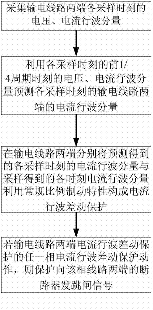
[0028] figure 1 It is a flowchart of a transmission line differential protection method based on current traveling wave prediction in the present invention. In this embodiment, the three-phase voltage traveling wave component u of the transmission line at each sampling time at the detection point of substation m is collected mA (t), u mB (t), u mC (t), three-phase current traveling wave component i mA (t), i mB (t), i mC (t); collect the three-phase voltage traveling wave component u of the transmission line at each sampling moment at the n substation detection point nA (t), u nB (t), u nC (t), three-phase current traveling wave component i nA (t), i nB (t), i nC (t).

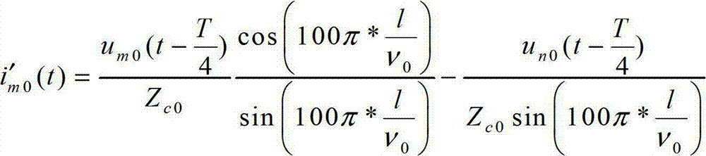
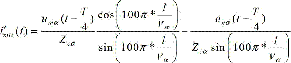
[0029]Using phase mode transformation, the three-phase voltage traveling wave components and three-phase current traveling wave components at each sampling time at the...


PUM


Abstract

The present invention relates to the technical field of electric power system relay protection. Disclosed is a current traveling wave prediction-based method for electric power transmission line differential protection. The method: first, voltages and current traveling wave components of two ends of an electric power transmission line at sampling moments are collected; the voltages and current traveling wave components of the first 1 / 4 cycle moments of the sampling moments are utilized to predict the current traveling wave components of the two ends of the electric power transmission line at the sampling moments; respectively at the two ends of the electric power transmission line, a current traveling wave differential protection is constituted from the current traveling wave components of the sampling moments acquired via prediction and the current traveling wave components of the moments acquired via sampling by means of utilizing conventional proportional braking characteristics; if any one current traveling wave differential protection phase of the current traveling wave differential protection at the two ends of the electric power transmission line is activated, then protecting by transmitting a trip signal to circuit breakers at the two ends of the phase of the transmission line. The method of the present invention utilizes the voltages and current traveling wave components at the first 1 / 4 cycle moments of the sampling moments to predict and acquire the current traveling wave components of the electric power transmission line at the sampling moments, obviates the need for an interpolation operation to arrive at the current traveling wave components of the sampling moments, reduces the amount of traveling wave protection computation, is capable of completing a traveling wave fault protection function within a short data window of 1 / 4 cycle, is rapid in activating the protection, and is applicable in the traveling wave protection during the entire process of a transient fault of electric power transmission lines of various voltage levels.

Description

technical field [0001] The invention relates to a transmission line differential protection method and, in particular, a transmission line differential protection method based on current traveling wave prediction. Background technique [0002] Because it is not affected by the system operation mode and grid structure and has a natural phase selection function, the current differential protection has always been the main protection of various voltage levels of transmission lines. In the 220kV and below voltage level transmission lines, because the distributed capacitance current along the transmission line is very small, the distributed capacitance has little influence on the operation performance of the current differential protection. However, the voltage and current transmission of EHV / UHV AC transmission lines has an obvious wave process, and the distributed capacitance current along the line is very large. The protection is faced with the large starting current of the c...

Claims


Application Information

Patent Timeline
Patent Type & Authority Patents(China)
IPC IPC(8): H02H7/26
CPCH02H7/265
Inventor 曾惠敏王永明郑志煜吴善班佘剑锋潘立志俞书献
Owner STATE GRID CORP OF CHINA
Why Eureka
Try Eureka