
Circuit and method for ensuring normal operation of light source modules

A technology that works normally and light source modules, applied in the field of electronics, can solve problems such as narrow application range

Inactive Publication Date: 2012-09-26
HISENSE VISUAL TECH CO LTD
View PDF6 Cites 9 Cited by
  • Summary
  • Abstract
  • Description
  • Claims
  • Application Information

AI Technical Summary

Problems solved by technology

[0007] The embodiment of the present invention provides a circuit for ensuring the normal operation of the light source module and a method for ensuring the normal operation of the light source module, which solves the problem of the narrow application range of the method of parallel connection of voltage regulator diodes on the light source module in the prior art. technical problem

Method used


Image

  • Circuit and method for ensuring normal operation of light source modules
  • Circuit and method for ensuring normal operation of light source modules
  • Circuit and method for ensuring normal operation of light source modules

Examples


Embodiment 1

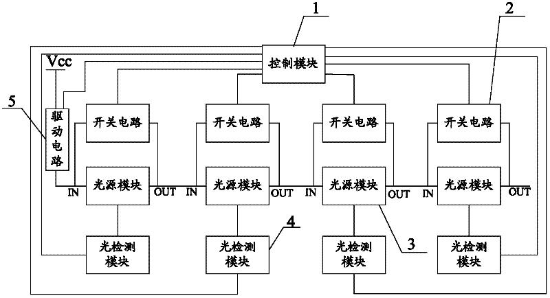
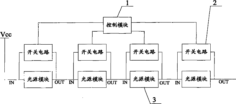
[0067] Such as figure 1 As shown, the circuit for ensuring the normal operation of the light source module provided by the embodiment of the present invention includes a control module 1 and a switch circuit 2 connected to the control module 1, wherein:

[0068] The switch circuit 2 is connected between the power input terminal IN and the power output terminal OUT of at least one light source module 3 among two or more light source modules 3 connected in series;

[0069] When the switch circuit 2 is disconnected, the light source module 3 works normally;

[0070] When the switch circuit 2 is turned on, the light source module 3 is short-circuited by the switch circuit 2;

[0071] The control module 1 is used to control the switch circuit 2 connected between the power input terminal IN and the power output terminal OUT of the failed light source module 3 when one of the light source modules 3 fails, and switch the switch circuit 2 from off to conduction.

[0072] In this emb...

Embodiment 2

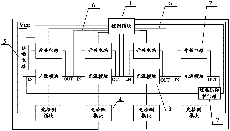
[0103] Such as Figure 6 and Figure 7 As shown, this embodiment is basically the same as Embodiment 1, and the difference is that the circuit for ensuring the normal operation of the light source module in this embodiment also includes a light detection module 4, wherein:

[0104] The light detection module 4 is used to detect the total light output value of two or more (two or more including two) light source modules 3, and input the light output value into the control module 1;

[0105] The control module 1 is also used to control and connect to each light source module one by one when the total light output value of two or more light source modules 3 does not meet the preset normal total light output value of two or more light source modules 3 3 The switch circuit 2 between the power input terminal IN and the power output terminal OUT switches the switch circuit 2 from off to on, and after the switch circuit 2 is turned on, the total light output value of two or more ligh...

Embodiment 3

[0109] Such as Figure 8 As shown, this embodiment is basically the same as Embodiment 1, and the difference is that in this embodiment, more than two (more than two including two) light detection modules 4 are arranged in the circuit for ensuring the normal operation of the light source module, Wherein at least one light detection module 4 is used to detect the total light output value of two or more light source modules 3 .

[0110] Among the multiple light source modules 3 connected in series, some light source modules 3 share one light detection module 4 , and each of the remaining light source modules 3 corresponds to one light detection module 4 . In this way, an appropriate number of light source modules 3 can be selected according to the number of light source modules 3. For example, if there are an odd number of, for example, seven light source modules 3, one light detection module 4 can be shared by every three, and the last remaining one can pass through a Light de...


PUM


Abstract

The present invention provides a circuit and a method for ensuring normal operation of light source modules, relating to the technical field of electronics and solving a technical problem of narrow application scope in the prior art. The circuit for ensuring the normal operation of the light source modules comprises a control module and switching circuits. The switching circuits are connected between an electricity input end and an electricity output end of one light source module of at least two light source modules which are in series with each other. When the switching circuits are off, the light source modules operate normally; when the switching circuits are on, the light source modules are shorted out by the switching circuits. The control module, when a fault of one of the light source modules occurs, is used to control the switching circuit that is connected between the electricity input end and the electricity output end of the light source module having a fault, and to switch the switching circuit from off to on status. The circuit and the method are applied to the ensuring of the normal operation of light source modules which are formed by a plurality of modules mutually connected in series.

Description

technical field [0001] The invention relates to the field of electronic technology, in particular to a circuit for ensuring the normal operation of a light source module and a method for ensuring the normal operation of the light source module. Background technique [0002] With the rapid development of electronic technology, electronic equipment or electronic devices with a light source module composed of light source modules connected in series (such as LED lamps) inside are more and more widely used. [0003] When the light source modules (such as LED lamps) are used in series, the power input end of the light source module in the light source module composed of a plurality of light source modules connected in series is connected to the power output end of the adjacent light source module, and / or , the power output end of the light source module is connected to the power input end of the adjacent light source module. Due to the light source modules connected in series, t...

Claims


Application Information

Patent Timeline
Patent Type & Authority Applications(China)
IPC IPC(8): H05B37/02H05B37/04
CPCY02B20/42Y02B20/40
Inventor 张海翔陈昱刘卫东郭大勃
Owner HISENSE VISUAL TECH CO LTD
Learn More