Mechanical pipe fitting end part forming machine

A mechanical and forming machine technology, applied in the field of pipe fitting end processing equipment, can solve the problems of quality influence and easy wear of pipe fitting end processing

Inactive Publication Date: 2012-10-03
王俊强
View PDF3 Cites 5 Cited by
  • Summary
  • Abstract
  • Description
  • Claims
  • Application Information

AI Technical Summary

Problems solved by technology

However, since the die is directly installed on the slider of the slider-crank mechanism, the slider of the slider-crank mechanism is subject

Method used


Image

  • Mechanical pipe fitting end part forming machine
  • Mechanical pipe fitting end part forming machine

Examples


Embodiment Construction

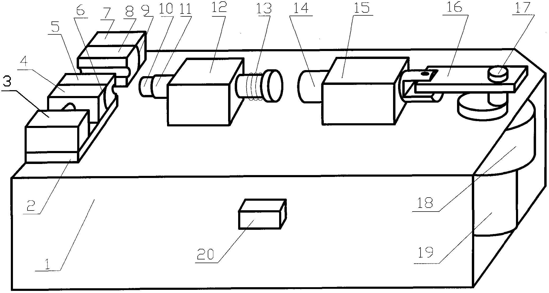
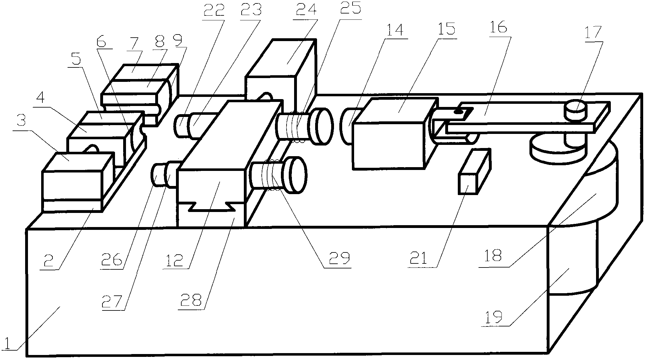
[0016] figure 1 A first embodiment of the present invention is shown. The present embodiment comprises a fuselage 1, a motor 19, an electric device for starting and stopping the motor, a speed reduction device 18, a crank slider mechanism, a clamping die device and a die device for processing pipe ends. In this embodiment, the clamping mold device mainly includes the fixed clamping mold base 7, the movable clamping mold base 4, the clamping mold 8, the clamping mold 5, the slideway 2 of the mobile clamping mold base 4, the cylinder 3, etc. . The punching die device mainly includes a punching die 10, a punching die slider 11 for installing the punching die 10, a slider seat 12 for installing the punching die slider 11, a return spring 13 for the punching die slider 11, and the like. The slider crank mechanism mainly includes a slider 14, a slider seat 15, a connecting rod 16, a crank 17 and the like. The die slide block 11 is cylindrical, and the position 9 where the fixed c...


PUM


Abstract

The invention discloses a mechanical pipe fitting end part forming machine for processing pipe fitting end parts, which comprises a machine body (1), a motor (19), a motor operating electrical unit, a deceleration device (18), a slider crank mechanism, a clamp pipe mould device, and a stamping die device for processing the pipe fitting end parts, wherein the stamping die device is mounted on a stamping die sliding block; the stamping die sliding block is not the sliding block (14) of the slider crank mechanism; and the sliding block (14) of the slider crank mechanism drives the stamping die sliding block to move forwards, and is driven by the motor (19) and the deceleration device (18). The stamping die sliding block only bears forward and backward force, so that the pipe fitting machining precision can not be impacted by the abrasion on the sliding block (14) of the slider crank mechanism used for a long time.

Description

technical field [0001] The invention relates to a pipe fitting end processing equipment, in particular to a mechanical pipe fitting end forming machine. Background technique [0002] At present, there is a mechanical pipe fitting end forming machine for pipe end processing in the factory, which mainly includes the fuselage, motor, motor start-stop electrical device, deceleration device, crank slider mechanism, pipe clamping die device and pipe end Die device for processing. The clamping die device can be clamped by hydraulic pressure, or by manual or wedge iron. When working, the pipe fittings are first positioned by the clamping die device, and after the motor is boosted by the deceleration device, the punching die on the slider is driven by the crank slider mechanism to expand the end of the pipe fittings, pre-install ferrules, etc., and the motor starts and stops the electrical appliances The device includes a contactor and a jog button, and the motor is controlled by t...

Claims


Application Information

Patent Timeline
IPC IPC(8): B21D22/02B21D39/00B21D41/00
Inventor 王俊强
Owner 王俊强
Why Eureka
Try Eureka