Self-propelled hydraulic plate for conveying tower drum

A hydraulic plate and self-propelled technology, which is applied in the direction of tilting and carrying vehicles, can solve problems such as difficult to avoid obstacles, rollovers, and restrictions on tower transportation, so as to avoid road reconstruction and remove obstacles. Technical and economic value, the effect of guaranteeing performance

Inactive Publication Date: 2012-10-03
CHONGQING YAJIE TRANSPORTATION
View PDF10 Cites 6 Cited by
  • Summary
  • Abstract
  • Description
  • Claims
  • Application Information

AI Technical Summary

Problems solved by technology

[0003] 1. Since the small-diameter end of the tower is about 15m in the air, this results in a large rear sweep area of ​​the Z-type high-low plate, and because the Z-type high-low plate does not have the steering function, and the steering angle of ordinary tractors is relatively limited, so As a result, the turning radius of the Z-shaped high-low plate is relatively large, and the turning radius of the road is required not to be too small
If the curve radius of the road is too small, you need to modify the curve radius of the road when you want to pass. However, road reconstruction involves many problems, such as compensation for demolition and ...

Method used


Image

  • Self-propelled hydraulic plate for conveying tower drum
  • Self-propelled hydraulic plate for conveying tower drum
  • Self-propelled hydraulic plate for conveying tower drum

Examples


Embodiment 1

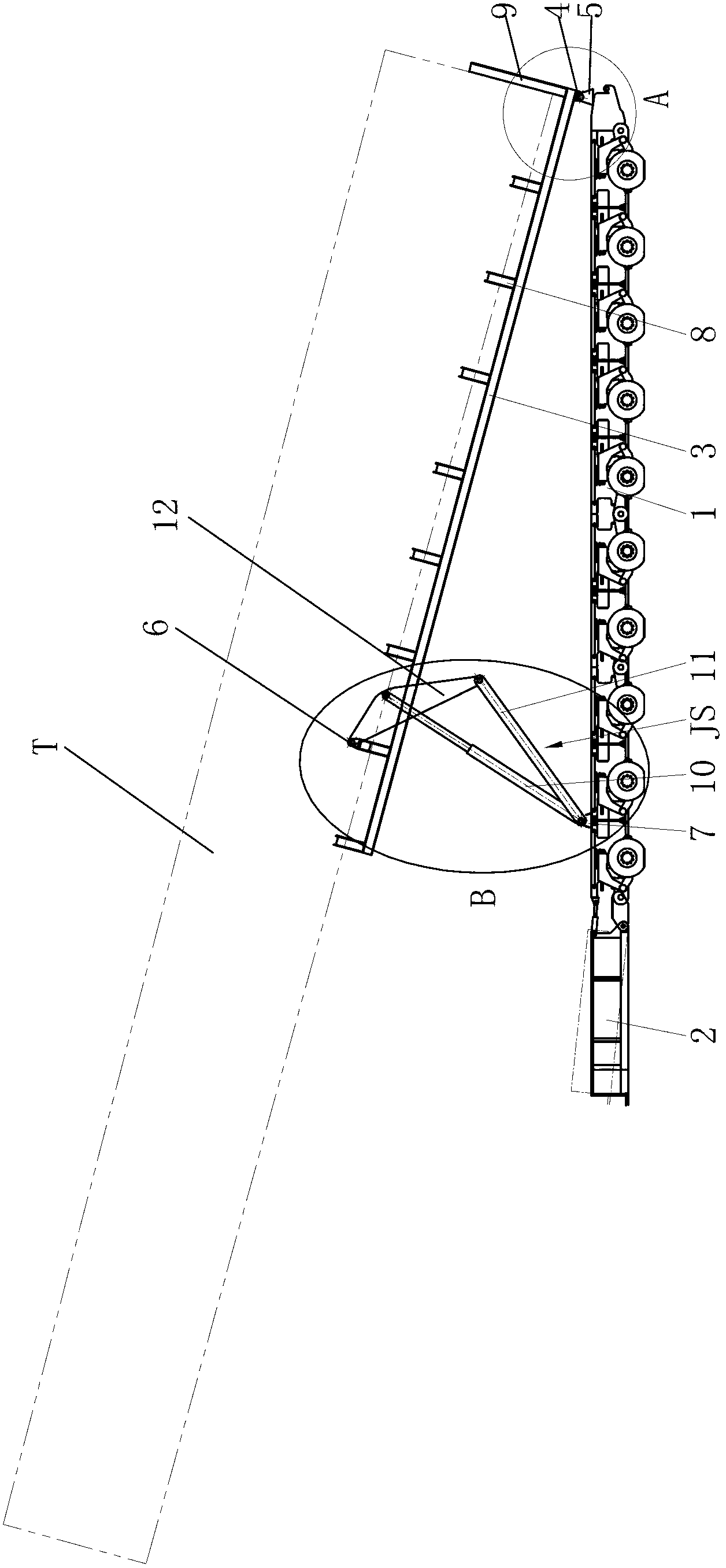
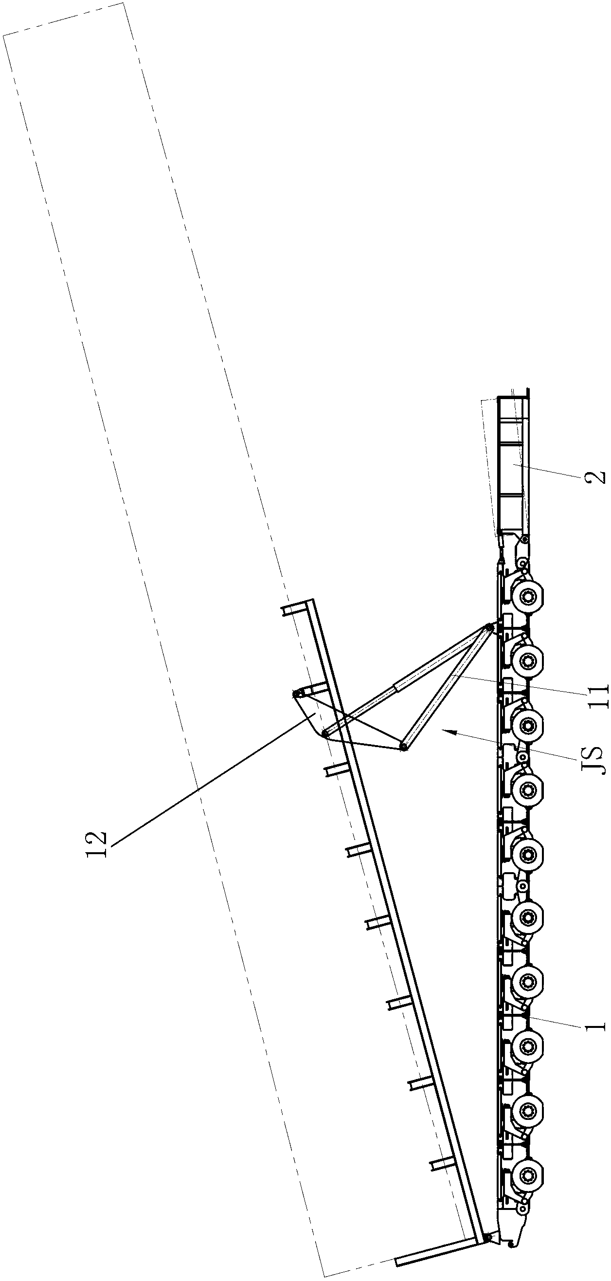
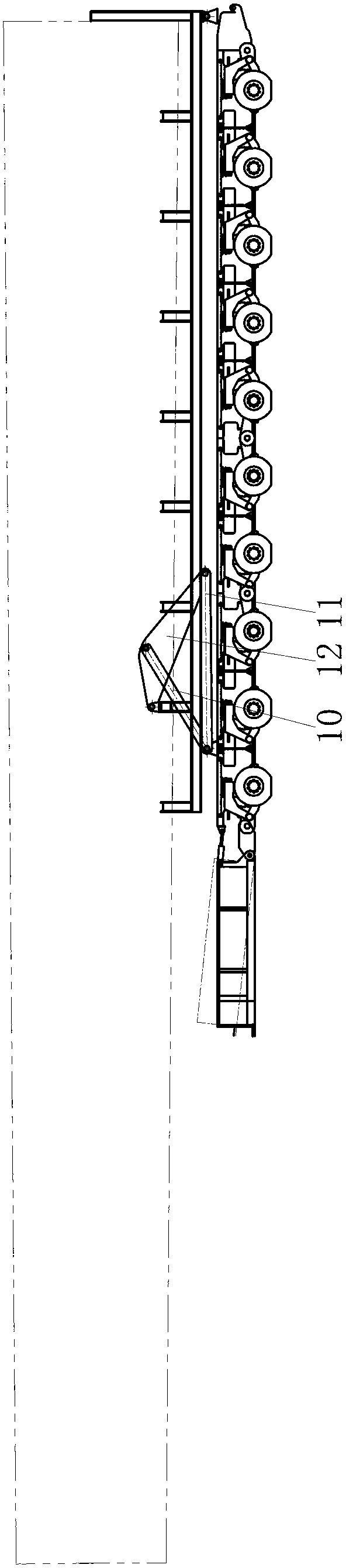
[0030] From Figures 1 to 7It can be seen that this embodiment consists of a hydraulic plate 1, a power module 2, a support frame 3, a first lug 4, a second lug 5, a third lug 6, a fourth lug 7, a support block 8, and a tower The baffle plate 9 and the lifting tool JS are composed, wherein the hydraulic plate 1 adopts the existing structure. When the hydraulic plate 1 encounters a bumpy road, its wheels can move up and down, so that the upper surface of the hydraulic plate 1 can be kept horizontal. And the specific structure of the hydraulic plate 1 will not be repeated here. In order to pull the hydraulic plate 1 and provide hydraulic pressure for the wheels of the hydraulic plate 1 to move up and down, a power module 2 is specially arranged at the front end of the hydraulic plate 1. The power module 2 is an existing structure, and the power module 2 and The hydraulic plate 1 together constitutes a self-propelled hydraulic plate, and the specific connection structure between...

Embodiment 2

[0037] refer to Figures 1 to 7 shown, combined with Figure 5 It can be seen that in this embodiment, the above-mentioned lifting tool JS is an oil cylinder, the piston rod of the oil cylinder is hinged to the third lug 6, and the cylinder liner of the oil cylinder is hinged to the fourth lug 7, The rest of the structure of this embodiment is completely the same as that of Embodiment 1, and will not be repeated here.


PUM


Abstract

The invention discloses a self-propelled hydraulic plate for conveying a tower drum. A supporting frame is arranged on the upper part of a hydraulic plate body; a first support lug at the rear end of the supporting frame is hinged with a second support lug at the rear end of the upper plate surface of the hydraulic plate body; third support lugs in the front of supporting frame is connected with corresponding fourth support lugs through two corresponding lifting tools; and the supporting frame can flip front and back around a hinged point at the rear end of the supporting frame under the driving of the two lifting tools. According to the self-propelled hydraulic plate, the hydraulic plate body, the supporting frame, supporting blocks, a tower drum baffle and the lifting tools are effectively combined, so that the tower drum T can successfully avoid obstacles on two sides of a road when the turning radius is reduced; the troubles that the road is required to be changed, and the obstacles are required to be removed are well eliminated; safety accidents can be avoided because the tower drum T can be kept in a horizontal state when passing by a bumpy road; and therefore, the tower drum T can be conveniently conveyed. The self-propelled hydraulic plate is simple in structure and easily implemented, and has a good technology and economic value.

Description

technical field [0001] The invention belongs to the field of wind power generator transportation, and in particular relates to a hydraulic plate used for transporting a wind power generator tower. Background technique [0002] At present, when transporting the tower of the wind power generator, the tower is generally directly fixed on the Z-shaped high-low plate, and the large-diameter end of the tower faces forward, while the small-diameter end of the tower faces backward, and the tower is suspended for about 15m. At the same time, the Z-type high-low board does not have a steering function, and the Z-type high-low board is towed by an ordinary tractor with a steering function. In the actual transportation process, we found that the above technical solutions to transport the tower have the following shortcomings: [0003] 1. Since the small-diameter end of the tower is about 15m in the air, this results in a large rear sweep area of ​​the Z-type high-low plate, and because...

Claims


Application Information

Patent Timeline
IPC IPC(8): B60P1/16
Inventor 罗庆肖宏
Owner CHONGQING YAJIE TRANSPORTATION
Why Eureka
Try Eureka