

Equipment and method for assisting in vehicle driving
A technology of vehicle driving and auxiliary equipment, which is applied to vehicle components, transportation and packaging, etc., which can solve the problems of high cost, high device requirements, and limited early warning function, and achieve the effect of reducing requirements and expanding the visual range
- Summary
- Abstract
- Description
- Claims
- Application Information
AI Technical Summary
Problems solved by technology
Method used
Image

Examples
Embodiment 1
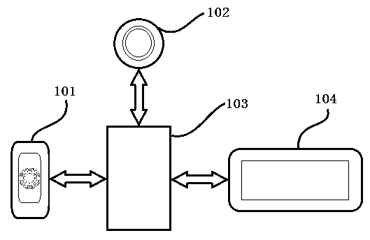
[0016] An implementation of vehicle driving assistance equipment in this application can refer to figure 1 , including an infrared pyrosensor 101, a multispectral camera 102, a processor 103 and a display device 104.
[0017] The infrared pyrosensor 101 is used as a first detection device for detecting objects within a first distance range and generating a corresponding first detection signal. The first distance is the sensing distance of the infrared pyrosensor 101 . In other embodiments, other devices capable of detecting object distances may be used as the first detection device, such as sonar or radar.
[0018] The multispectral camera 102 is used as a first image acquisition device for acquiring images and generating corresponding image data. The photosensitive chip of the multi-spectral camera 102 can sense infrared and visible light at the same time, and the collected infrared image and visible light image overlap in size and orientation, so the image data generated by...
Embodiment 2
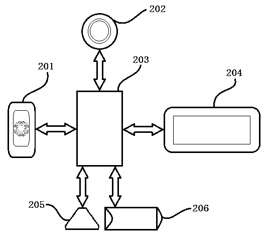
[0032] Another embodiment of the vehicle driving assistance device in this application can refer to image 3 Compared with Embodiment 1, the difference is that in addition to including an infrared pyrosensor 201, a multispectral camera 202, a processor 203 and a display device 204, it also includes a sound alarm device 205 and a vibration alarm device 206 used as an alarm device.
[0033] The infrared pyrosensor 201 , the multispectral camera 202 and the display device 204 are similar to the infrared pyrosensor 101 , the multispectral camera 102 and the display device 104 in Embodiment 1, and will not be repeated here. In addition to the content of the processor 103 described in Embodiment 1, the processor 203 is also signal-connected to each alarm device, and is used to generate an alarm command according to the first detection signal, so as to trigger each alarm device to generate a corresponding alarm action. The sound alarm device 205 is used for making a sound according t...
Embodiment 3
[0038] Another embodiment of the vehicle driving assistance device in this application can refer to Figure 5 , including a two-stage infrared pyrosensor 301, a multispectral camera 302, a processor 303, a display device 304, an audio alarm device 305 and a vibration alarm device 306.
[0039] The multispectral camera 302 and the display device 304 are similar to the multispectral camera 102 and the display device 104 in Embodiment 1, and will not be repeated here.
[0040] The two-stage infrared pyroelectric sensor 301 is used as the first detection device, and consists of two sets of passive infrared (PIR, Passive Infrared) sensors whose detection distances are respectively the first distance range and the second distance range, and the second distance range is greater than the first distance range scope. In this case, the first detection device can respectively detect objects within the first and second distance ranges, and generate corresponding first and second detection...
PUM
 Abstract
Description
Claims
Application Information