
Brake

A brake and cylinder technology, applied in hydraulic brakes, brake actuators, gear shifting mechanisms, etc., can solve the problems of occupying the rhythm and unable to completely eliminate errors, and achieve the effect of reducing the braking distance

Inactive Publication Date: 2012-10-03
CHINA NAT HEAVY MACHINERY RES INSTCO
View PDF4 Cites 7 Cited by
  • Summary
  • Abstract
  • Description
  • Claims
  • Application Information

AI Technical Summary

Problems solved by technology

Although this method can reduce the error, it will take up a beat, and it cannot completely eliminate the error.

Method used


Image

  • Brake
  • Brake
  • Brake

Examples


Embodiment 1

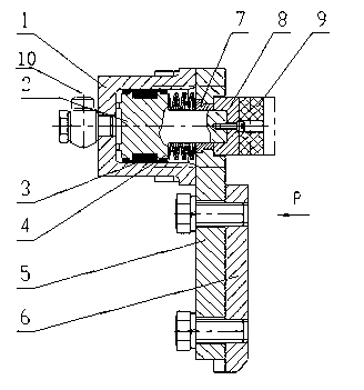
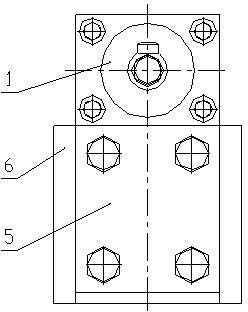
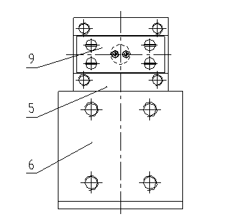
[0016] Such as figure 1 , 2 , 3, a brake is characterized in that: it at least includes a cylinder 1, a piston 2, a support plate 5, a bearing 6, a locking block 8, a brake pad 9, and the cylinder 1 is fixedly connected with the support plate 5, There is a piston 2 in the cylinder body 1, and the right end of the piston 2 is fitted in the guide sleeve 7, forming a piston cylinder with the cylinder body 1 and the support plate 5, the guide sleeve 7 is fixedly connected with the support plate 5, and the disc spring 4 is formed by the piston 2 and the support plate 5 In the cavity surrounded by the support plate 5, the locking block 8 is fixedly connected to the end of the piston 2, the brake pad 9 is glued to the locking block 8, the support 6 is fixedly connected to the support plate 5, and the cylinder body 1 is connected through the hole 10 hydraulic or pneumatic systems.

Embodiment 2

[0018] It is basically the same as Embodiment 1, the difference is that there is a notch at the contact between the support plate 5 and the locking block 8, which acts as a guide for the locking block 8 when the brake is working. The bearing 6 is welded at a suitable position of the tractor, and a notch is arranged on it to overcome the shear stress generated during braking. The brake pad 9 corresponds to the roller braking surface of the tractor, and the distance from the braking surface is 2mm. There is a seal 3 between the piston 2 and the cylinder 1 to prevent leakage of high-pressure oil or compressed air.

[0019] When braking, the hydraulic or pneumatic system controls the high-pressure oil or compressed air to enter from the hole 10. Under the action of the high-pressure oil or compressed air, the piston 2 protrudes outwards against the resistance of the disc spring 4, thereby pushing the brake pads 9 close. The braking surface of the roller table achieves the purpose...


PUM


Abstract

The invention discloses a brake which belongs to a brake on an aluminum extrusion production line and particularly belongs to a brake adopting high pressure oil or compressed air as brake power for braking and a disk spring for returning, in order to solve the problem of inaccurate stop position of a tractor. The brake at least comprises a cylinder (1), a piston (2), a support plate (5), a support (6), a locking block (8) and a brake pad (9). When the brake is in work, hydraulic oil or compressed air enters the cylinder (1) through a hole (10) of the cylinder (1) and pushes the piston (2) to drive the brake pad (9) onto a braking surface, thereby implementing rapid braking. According to the brake, the tractor can rapidly, accurately and safely stop at a position required by a process; and the brake is high in automatic degree, reliable in braking, and convenient to operate.

Description

technical field [0001] The invention belongs to a brake on an aluminum extrusion production line, in particular to a brake which adopts high-pressure oil or compressed air as the braking power for braking and is reset by a disc spring. Background technique [0002] In the production process of the aluminum extrusion machine, in order to eliminate the uneven flow of metal at the die mouth, a tractor is generally installed. When the tractor is working, the traction speed matches the extrusion speed. In order to meet the extrusion beat, the return speed of the tractor even reaches 3m / s, so that the tractor needs to stop at the position required by the process quickly, accurately and safely. [0003] The current technology is to use the frequency converter to control the start and stop of the traction motor through the signal provided by the rotary encoder or the code ruler according to the process requirements, and then control the start and stop of the traction machine. D...

Claims


Application Information

Patent Timeline
Patent Type & Authority Applications(China)
IPC IPC(8): F16D55/10F16D65/18F16D121/04
Inventor 杜学斌权晓惠张君卫凌云
Owner CHINA NAT HEAVY MACHINERY RES INSTCO
Learn More