Transmission device for changing straight reciprocating motion into rotary motion

A technology of linear reciprocating motion and rotary motion, applied in the direction of transmission, belt/chain/gear, mechanical equipment, etc., can solve the problems of high installation accuracy, difficult installation, high price, etc., and achieve the effect of adjustable speed

Inactive Publication Date: 2012-10-03
ZHEJIANG UNIV OF TECH
View PDF3 Cites 9 Cited by
  • Summary
  • Abstract
  • Description
  • Claims
  • Application Information

AI Technical Summary

Problems solved by technology

[0003] In order to overcome the problems of large volume, high installation precision requirements, difficult installation, large energy loss, easy slipping and high price existing in the existing mechanism, the present invent

Method used


Image

  • Transmission device for changing straight reciprocating motion into rotary motion
  • Transmission device for changing straight reciprocating motion into rotary motion
  • Transmission device for changing straight reciprocating motion into rotary motion

Examples


Embodiment Construction

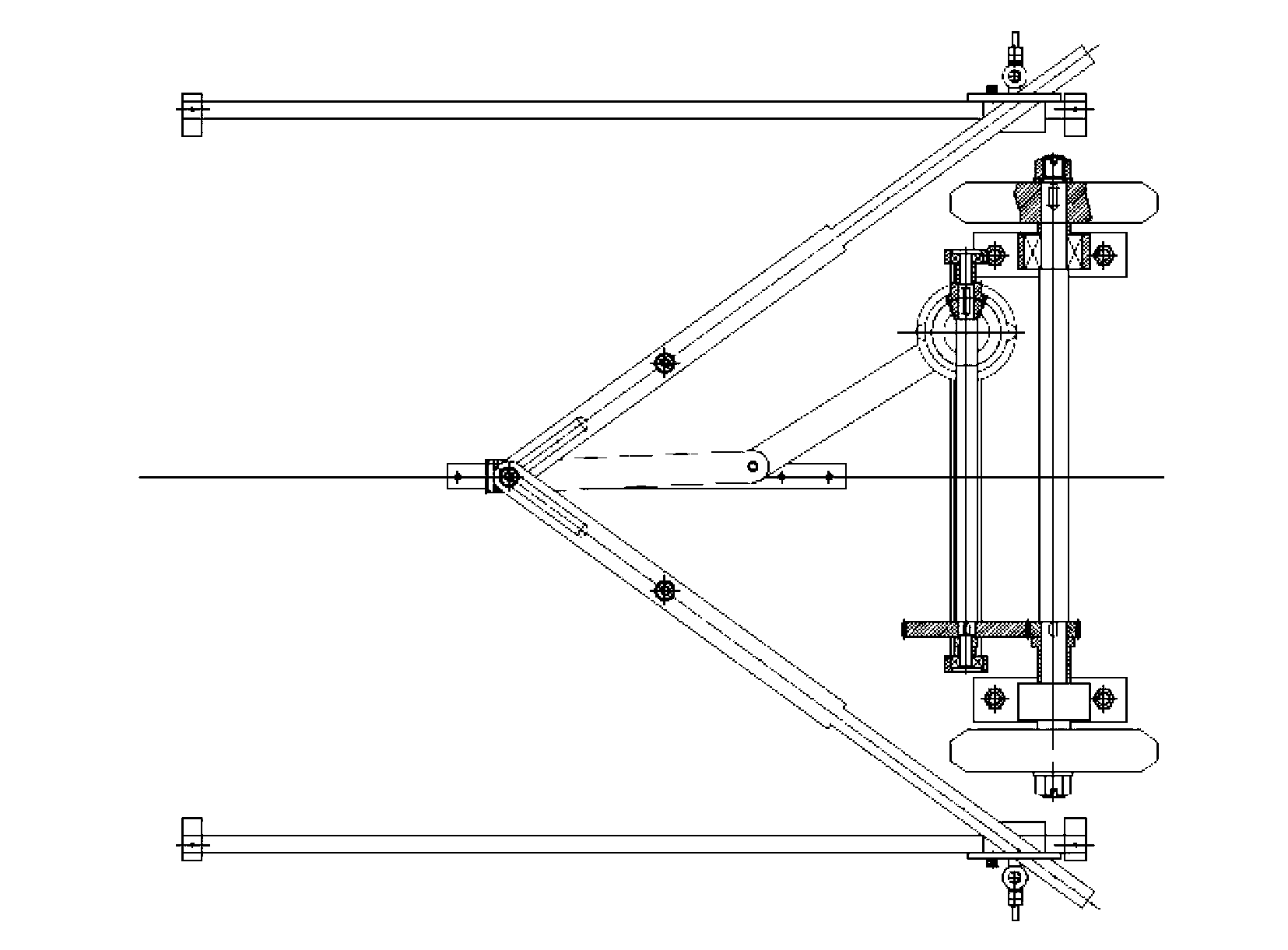
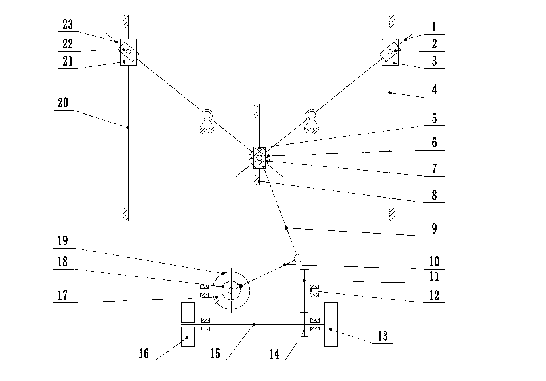
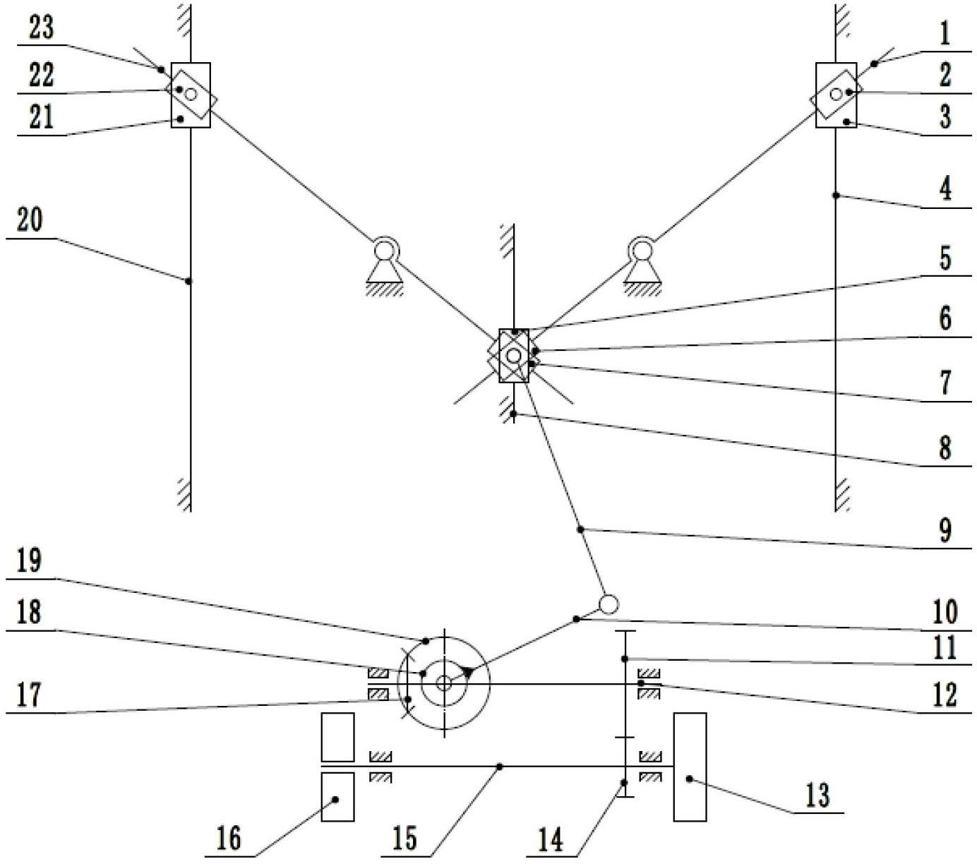
[0014] refer to figure 1 and figure 2 , the linear reciprocating motion is converted into a rotary motion transmission, including a first lever mechanism, a second lever mechanism, a rocker slider mechanism, a one-way clutch 18, a bevel gear mechanism and a spur gear mechanism; the first lever mechanism includes the first lever mechanism A transmission lever 1, the first slide block 2 and the sixth slide block 6, the second lever mechanism comprises the second transmission lever 23, the second slide block 22 and the seventh slide block 7, and the rocker slide block mechanism comprises The fifth slide block 5, connecting rod 9 and rocking bar 10, described bevel gear mechanism comprises driving bevel gear 19 and driven bevel gear 17, and described spur gear mechanism comprises driving spur gear 11 and driven spur gear 14;

[0015] The first slider 2 and a third slider 3 are hinged at the same point, and the second slider 22 and a fourth slider 21 are hinged at the same point;...


PUM


Abstract

The invention discloses a transmission device for changing straight reciprocating motion into rotary motion. The transmission device for changing the straight reciprocating motion into the rotary motion comprises a first lever mechanism, a second lever mechanism, a rocker sliding block mechanism, a one-way clutch, a bevel gear mechanism and a spur gear mechanism. The first lever mechanism comprises a first transmission lever, a first sliding block and a sixth sliding block, the second lever mechanism comprises a second transmission lever, a second sliding block and a seventh sliding block, the rocker sliding block mechanism comprises a fifth sliding block, a connecting rod and a rocker, the bevel gear mechanism comprises a driving bevel gear and a driven bevel gear, and the spur gear mechanism comprises a driving spur gear and a driven spur gear. The transmission device for changing the straight reciprocating motion into the rotary motion can change the straight reciprocating motion into the rotary motion in a small space and is adjustable in rotation speed.

Description

technical field [0001] The invention relates to a transmission device for converting linear reciprocating motion into rotary motion. Background technique [0002] At present, the common mechanisms for converting linear reciprocating motion into rotary motion include rack and pinion, crank slider, ball screw and other mechanisms. Although the rack and pinion mechanism has high efficiency, it requires high installation accuracy and is relatively laborious. The crank-slider mechanism must have a dead point, and the force applied to the crank at different angular positions varies greatly. When the ball screw ball sleeve drives the screw, the energy loss is large, it is easy to slip, and the price is relatively high. Contents of the invention [0003] In order to overcome the problems of large volume, high installation precision requirements, difficult installation, large energy loss, easy slipping and high price existing in the existing mechanism, the present invention provi...

Claims


Application Information

Patent Timeline
IPC IPC(8): F16H37/14
Inventor 周忠彬庄载椿黄智奇马骏鲁陈璐金明生袁屹
Owner ZHEJIANG UNIV OF TECH
Why Eureka
Try Eureka