Precision measuring method of high-precision star sensor
A technology of star sensor and precision measurement, which is applied in the direction of measuring devices and instruments, and can solve the problems of high price and complicated operation
Active Publication Date: 2012-10-03
北京天银星际科技有限责任公司
5 Cites 16 Cited by
AI-Extracted Technical Summary
Problems solved by technology
[0005] For this reason, the present invention provides a kind of precision measurement method of high-precision star sensor, the precision measurement method of described high-precision star sensor can realize the measurement of roll precision and pointing precision of star sensor easily and solve the problem of traditional The test method of the t...
Method used
Can find out thus, need the navigation star of high precision in real star sensor measurement system, in order to guarantee the coverage of star sensor field of view simultaneously, need to rotate system to realize that navigation star appears in the difference of field of view In terms of position, for this reason, the traditional calibration and testing methods use a single star simulator and a high-precision turntable to realize the imaging of star points in different fields of view, and then realize the calibration and testing of the system. In order to cover the whole system more realistically and comprehensively, according to an embodiment of the present invention, the inventor has used the combination of the real starry sky measurement results of the star sensor and the mode of the earth's rotation, thereby making the precision measurement for the star sensor more realistic and accurate. precise.
[019...
Abstract
The invention discloses a precision measuring method of a high-precision star sensor, and the method comprises the steps of fixing the star sensor for storing a star map on the earth and ensuring that a rolling shaft of the star sensor points to zenith; obtaining a first optimum posture matrix qi of the star sensor and an actual shooting time corresponding to the star map according to a direction vector of a navigation star under a coordinate system of the star sensor and a direction vector under the J2000.0 right-angle coordinate system; obtaining a second optimum posture matrix according to qi; obtaining a precision measuring conversion matrix associated to the star sensor according to the actual shooting time of the star sensor and the precession, nutation and autoroatation of the earth; obtaining a precision measuring matrix according to the second optimum posture matrix and the precision measuring conversion matrix; determining a three-axis pointing vector of the star sensor according to the precision measuring matrix; obtaining an angle respectively between three optimum pointing vectors of the star sensor at the actual shooting time and an X-axis vector, a Y-axis vector and a Z-axis vector of the star sensor according to the three-axis pointing vector; and obtaining the rolling precision and the pointing precision of the star sensor according to the angles.
Application Domain
Measurement devices
Technology Topic
Star sensorNutation +3
Image
Examples
- Experimental program(1)
Example Embodiment
[0076] The embodiments of the present invention will be described in detail below. Examples of the embodiments are shown in the accompanying drawings, wherein the same or similar reference numerals indicate the same or similar elements or elements with the same or similar functions. The embodiments described below with reference to the drawings are exemplary, and are only used to explain the present invention, but should not be understood as limiting the present invention.
[0077] In the description of the present invention, it should be understood that the terms "center", "longitudinal", "transverse", "upper", "lower", "front", "rear", "left", "right", " The orientation or positional relationship indicated by "vertical", "horizontal", "top", "bottom", "inner", "outer", etc. are based on the orientation or positional relationship shown in the drawings, and are only for the convenience of describing the present invention and simplifying The description does not indicate or imply that the pointed device or element must have a specific orientation, be constructed and operated in a specific orientation, and therefore cannot be understood as a limitation of the present invention.
[0078] It should be noted that, in addition, the terms "first" and "second" are only used for descriptive purposes, and cannot be understood as indicating or implying relative importance or implicitly indicating the number of indicated technical features. Thus, the features defined with "first" and "second" may explicitly or implicitly include one or more of these features. Further, in the description of the present invention, unless otherwise specified, "plurality" means two or more.
[0079] In order to elaborate on the accuracy measurement method of the high-precision star sensor of the present invention, the working principle of the star sensor according to an embodiment of the present invention will first be introduced below.
[0080] Star sensor measurement principle
[0081] The attitude of the star sensor usually refers to the pointing relative to a specified coordinate system, and the most commonly used is the pointing relative to the celestial inertial coordinate system. The star sensor relies on measuring the orientation of the navigation star in the spacecraft coordinate system to determine the attitude of the spacecraft where the star sensor is located relative to the inertial space. In the working state, first measure the vector of the navigation star in the star sensor coordinate system, and then identify the vector corresponding to the navigation star in the inertial coordinate system through the obtained star map. By comparing the vector relationship of the corresponding navigation stars in the two coordinate systems, the transformation matrix from the inertial coordinate system to the spacecraft coordinate system can be obtained, that is, the attitude of the spacecraft in the inertial coordinate system.
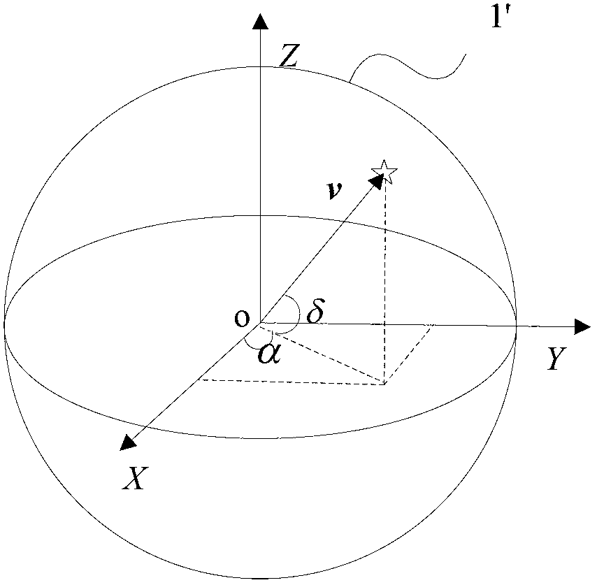
[0082] The star is the reference benchmark for the work of the star sensor. After many years of astronomical observations, each star has its own relatively fixed position in the celestial sphere 1'. figure 1 It is a schematic diagram of the coordinate vector of the star in the celestial spherical coordinate system and the rectangular coordinate system. Such as figure 1 As shown in the celestial sphere, the right ascension and declination of the celestial spherical coordinates are expressed. The coordinates of the star in the celestial spherical coordinate system can be written as (α, δ). According to the relationship between rectangular coordinates and spherical coordinates, the direction vector of each star in the celestial rectangular coordinate system can be obtained as:
[0083] v = cos α cos δ sin α cos δ sin δ .
[0084] Stars that meet the imaging conditions of the star sensor are selected from the star database to form a navigation star, and thus form a navigation star catalog. According to an embodiment of the present invention, the navigation star catalog can be solidified into the memory of the star sensor at one time during the manufacturing process.
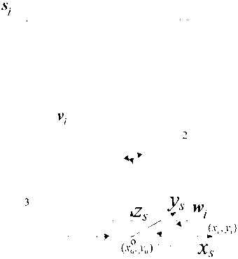
[0085] When the star sensor 1 is in a certain attitude matrix in the celestial coordinate system A, using the principle of small hole imaging of the star sensor, the navigator s can be measured through the lens 2 of the star sensor 1 i (The corresponding direction vector in the celestial coordinate system is v i ) The direction vector in the star sensor coordinate system is w i ,Such as figure 2 Shown in.
[0086] Such as figure 2 The position of the center of the rolling axis of the star sensor 1 on the detector (x 0 , Y 0 ), navigator s i The position coordinates on the detector 3 of the star sensor 1 are (x i , Y i ), the focal length of the star sensor is f, then w i The expression of the vector is as follows:
[0087] w i = 1 ( x i - x 0 ) 2 + ( y i - y 0 ) 2 + f 2 - ( x i - x 0 ) - ( y i - y 0 ) f
[0088] Ideally, it has the following relationship:
[0089] w i =Av i
[0090] Among them: A is the attitude matrix of the star sensor.
[0091] When more than two stars are observed, the attitude matrix A of the star sensor can be solved directly by the method such as QUEST, that is, the following objective function J(A q ) Reach the minimum value to find the optimal pose matrix A q :
[0092] J ( A q ) = 1 2 X i = 1 n λ i | | w i - A q v i | | 2
[0093] Where λ i Indicates the weighting coefficient, which satisfies ∑λ i = 1.
[0094] In this way, the optimal attitude matrix A of the star sensor in the inertial space can be calculated q.
[0095] It can be seen that a high-precision navigation star is required in a real star sensor measurement system. At the same time, in order to ensure the coverage of the star sensor's field of view, the system needs to be rotated to realize that the navigation star appears in different positions of the field of view. For this reason, the traditional calibration and test method uses a single-star simulator and a high-precision turntable to realize the imaging of the star points in different fields of view, and then realize the calibration and test of the system. In order to cover the entire system more realistically and comprehensively, according to an embodiment of the present invention, the inventor uses the combination of the real star sky measurement results of the star sensor and the mode of the earth's rotation, thereby making the precision measurement for the star sensor more realistic and accurate.
[0096] The motion of the earth will be described in detail below for the high-precision measurement and analysis of the star sensor according to the present invention.
[0097] The laws of the movement of the earth
[0098] The measurement method of the present invention uses the precise motion of the earth as the accuracy measurement reference of the star sensor, and strict analysis and calculation are required for the motion of the earth in the inertial space. image 3 It is the main coordinate system parameter of the earth moving in the celestial coordinate system.
[0099] Such as image 3 As shown, a imaginary large sphere with arbitrary radius centered on the earth is called "celestial sphere", the circle where the earth's equatorial plane intersects with the celestial sphere is called "celestial equator", and the circle where the orbital plane of the earth revolves around the sun and the celestial sphere intersects is called " Zodiac". The celestial equator intersects with the ecliptic at two points, and the sun's line of sight travels from the south of the celestial equator to the intersection of the north of the celestial equator and the celestial equator at the vernal equinox. The point where the sun travels from the north of the celestial equator into the south of the celestial equator and the celestial equator is called the autumnal equinox. The sun starts from the vernal equinox and travels along the ecliptic for a week and returns to the vernal equinox as a "tropical year."
[0100] If the Earth’s axis does not change its direction and the bifurcation does not move, the tropical year is equal to the sidereal year. But the earth’s axis moves slowly around the ecliptic, and the intersection line of the equatorial plane and the ecliptic plane also rotates on the ecliptic plane in the same period, such as image 3 As shown, the celestial north pole rotates clockwise around the yellow north pole with a radius of 23°26′21″. Because the earth’s revolution direction is opposite to the precession direction of the earth’s axis, the vernal equinox produces a slight westward shift every year, which is called in astronomy It is precession. The measurement and calculation results of modern astronomy show that the annual precession of the earth is 50.29″, so the north celestial pole rotates once around the yellow north pole in about 25765.
[0101] Similar to the motion model of the top, the earth’s rotation axis is precessing at the same time it is also nutating. The reason for its formation is more complicated. Generally speaking, it is caused by the gravity of other planets and the moon near the earth. Astronomical measurement results show that the nutation period is 18.6 years (6798 days), the nutation component of the ecliptic is 17.24″, and the oblique nutation perpendicular to the ecliptic is 9.21″. As a result, the coordinates of celestial bodies such as right ascension and declination are changed.
[0102] The rotation axis of the earth still has phenomena such as pole shift, but its periodic changes are all below 0.1", so the accuracy test relative to the star sensor can be ignored.
[0103] The movement of the earth in inertial space includes not only its own rotation around the earth's axis, but also the precession of the earth's axis around the yellow north pole, the nutation and polar shift of the earth's axis. The earth's revolution around the sun does not produce changes in the earth's axis in inertial space, and will not affect the test of the star sensor.
[0104] The establishment of the system coordinate system
[0105] The four coordinate systems of the celestial equatorial coordinate system, the epoch celestial ecliptic coordinate system, the earth-fixed coordinate system and the star sensor coordinate system used in the present invention will be described in detail below.
[0106] 1) Celestial equatorial coordinate system: using CRF (Celestial Reference Frame), considering the influence of precession and nutation, the celestial equatorial coordinate system is time-related. For the convenience of system analysis, the J2000.0 celestial equatorial coordinate system, referred to as J2000.0 Cartesian coordinate system, has been established internationally, which is represented by the symbol CRFJ2000, such as Figure 4 As shown in the CRFJ2000 coordinate system. The J2000.0 Cartesian coordinate system is the celestial equatorial coordinate system established at 12 o'clock in the geomechanical time on January 1, 2000, the Z axis points to the north pole of the earth, the X axis points to the vernal equinox at the time of establishment, the Y axis and the X axis and Z axis Meet the right-hand rule. The information about the navigation star of the star sensor is based on this. The position of the navigation star in the star sensor is represented by this coordinate system. Due to the influence of precession and nutation, the celestial coordinate system at different times will rotate accordingly. The celestial coordinate system at a certain moment can only be obtained by eliminating the influence of precession and nutation on the basis of J2000.0, which is represented by the symbol CRFT.
[0107] 2) The celestial ecliptic coordinate system of the epoch: expressed by ERF (Ecliptic Reference Frame), such as Figure 4 X in ERF , Y ERF And Z FRF Marked. The definition was established at 12 o'clock in geomechanical time on January 1, 2000, and remained fixed. The orbit of the earth around the sun is called the ecliptic, with the center of the earth as the center, the vernal equinox pointing to the establishment time as the X axis, and the plane perpendicular to the ecliptic as the Z axis. The Y axis, X axis, and Z axis satisfy the right-hand rule. The X-axis of the J2000 coordinate system is consistent with the X-axis of the ecliptic coordinate system. The Z-axis of the epoch celestial ecliptic coordinate system and the Z-axis of the J2000 coordinate system include an angle of 23°26′21″. The celestial equatorial coordinate system revolves around the epoch celestial sphere. The Z axis of the ecliptic coordinate system rotates at a speed of 50.29" per year, which is called precession.
[0108] 3) Ground-fixed coordinate system: The definition of the coordinate axis of the ground-fixed coordinate system is the same as that of the celestial coordinate system, but the difference is that as the earth moves, the ground-fixed coordinate system revolves around the Z axis of the earth (ie the Z axis of the celestial coordinate system). Approximately rotating at a constant speed, the angular velocity is Ω=7.292115×10 -5 rad/s. The ground-fixed coordinate system is used as Figure 4 It is represented by TRF (Terrestrial Reference Frame) shown in.
[0109] 4) Star sensor coordinate system: The star sensor coordinate system is fixed on the star sensor and moves with it. Its center is the detector center of the star sensor. The X axis and Y axis are respectively parallel to the rows and columns of the detector. The Z axis and the other two axes satisfy the right-hand rule, which is represented by SCF (Star tracker Coordinate Frame), such as Figure 4 X in SCF , Y SCF And Z SCF Shown. When in use, fix the star sensor with the earth and move with the earth-fixed coordinate system.
[0110] The navigation stars measured by the star sensor are all stars and are very far away. Therefore, the coordinate origins of the above four coordinate systems can be considered to be at the same point, and the transformation between the coordinate systems is only a rotation transformation. The basic method of rotation transformation is as follows:
[0111] Let (X, Y, Z) be the original coordinate system and (X', Y', Z') be the coordinate system after rotation, then
[0112] (X',Y',Z')=(X,Y,Z)·R(-θ)
[0113] Among them, the coordinate transformation base of the coordinate system rotating around the X axis, Y axis, and Z axis is:
[0114] R X ( θ ) = 1 0 0 0 cos θ sin θ 0 - sin cos θ ,
[0115] R Y ( θ ) = cos θ 0 - sin θ 0 1 0 sin θ 0 cos θ ,
[0116] R Z ( θ ) = cos θ sin θ 0 - sin θ cos θ 0 0 0 1 .
[0117] The accuracy measurement method of the star sensor and the high-precision star sensor of the present invention will be described in detail below with reference to the accompanying drawings.
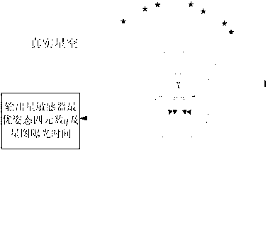
[0118] According to the star sensor 1 of the present invention, the star sensor 1 may have the output function of attitude quaternion and corresponding star map exposure time parameters, such as Figure 5 As shown, it is convenient to use the method and system of the present invention to measure the accuracy of the star sensor 1 in the process of using the star sensor 1.
[0119] According to the star sensor 1 of the present invention, the star sensor 1 may include a memory (not shown) in which a navigation star list composed of navigation stars is stored. To facilitate the implementation of the present invention, the navigation star table may be formed based on the J2000.0 rectangular coordinate system and the current time (T) of the test start time relative to the time J2000.0, after considering the navigation star visual motion parameters associated with the navigation star , The direction vector of the navigation star in the J2000.0 rectangular coordinate system (v CRFJ2000 )for:
[0120] v CRFJ 2000 = cos ( α + α ′ T ) cos ( δ + δ ′ T ) sin ( α + α ′ T ) cos ( δ + δ ′ T ) sin ( δ + δ ′ T ) .
[0121] According to an embodiment of the present invention, during the manufacturing process, for the convenience of subsequent considerations, the navigation star catalog based on the J2000.0 rectangular coordinate system and taking into account the navigation star's visual motion parameters can be solidified in the memory at one time .
[0122] Refer to below Image 6 To illustrate the accuracy measurement method of the high-precision star sensor. Such as Image 6 As shown in, the method for measuring the accuracy of the star sensor may include the following steps:
[0123] 1) Fix the star sensor on the earth, and make the rolling axis of the star sensor point to the zenith, and the star image is stored in the star sensor;
[0124] 2) According to the direction vector of the navigation star in the star sensor coordinate system and the direction vector in the J2000.0 rectangular coordinate system (v CRFJ2000 ) Obtain and output the first optimal attitude matrix q of the star sensor i =[q 1 q 2 q 3 q 4 ] And the actual shooting time of the corresponding star map (T+Δt i );
[0125] 3) According to the first optimal pose matrix q i Get the second optimal pose matrix A q (T+Δt i ):
[0126] A q ( T + Δt i ) = q 1 2 - q 2 2 - q 3 2 + q 4 2 2 ( q 1 q 2 + q 3 q 4 ) 2 ( q 1 q 3 - q 2 q 4 ) 2 ( q 1 q 2 - q 3 q 4 ) - q 1 2 + q 2 2 - q 3 2 + q 4 2 2 ( q 2 q 3 + q 1 q 4 ) 2 ( q 1 q 3 + q 2 q 4 ) 2 ( q 2 q 3 - q 1 q 4 ) - q 1 2 - q 2 2 + q 3 2 + q 4 2 ;
[0127] 4) According to the actual shooting time of the star sensor (T+Δt i ) And the earth’s precession, nutation and rotation to obtain the accuracy measurement conversion matrix associated with the star sensor
[0128] 5) Use the second optimal pose matrix A q (T+Δt i ) And the accuracy measurement conversion matrix Get accuracy measurement matrix A test ( T + Δt i ) = A q ( T + Δt i ) · R T + Δt i ;
[0129] 6) According to the accuracy measurement matrix (A test (T+Δt i )) to determine the three-axis pointing vector p(T+Δt i ):
[0130] p ( T + Δt i ) = A test ( T + Δt i ) T 1 0 0 0 1 0 0 0 1 ;
[0131] 7) According to the three-axis pointing vector p(T+Δt i ) To get the actual shooting time (T+Δt i ) Of the three optimal pointing vectors of the star sensor and the respective angles (α) of the X-axis, Y-axis, and Z-axis vectors of the star sensor i , Β i , Ε i );
[0132] 8) Put α i , Β i , Ε i Unified use η i Means that α i , Β i , Ε i Substitute into the following formula respectively η i Available σ X , Σ Y , Σ Z , The rolling accuracy of the star sensor is 3σ X Or 3σ Y , The pointing accuracy is 3σ Z ,among them
[0133] σ = X 0 n η i 2 n - 1 ,
[0134] n represents the total sampling times of the star sensor.
[0135] According to the accuracy measurement method of the high-precision star sensor of the embodiment of the present invention, the rolling accuracy and pointing accuracy of the star sensor can be easily measured, and the traditional test method is complicated to operate and requires expensive precision turntables and The star simulator is troublesome, and the measurement results are more accurate and authentic than the rotary measurement method, and the test accuracy can meet the requirements of the star sensor.
[0136] In the present invention, 3σ can be used to represent the three-axis accuracy, that is, the rolling accuracy is 3σ X Or 3σ Y , The pointing accuracy is 3σ Z. Moreover, in step (S1), by fixing the star sensor on the earth, in order to minimize the influence of the atmosphere, the star sensor is directly facing the zenith, so that the star sensor can output the corresponding output with the movement of the earth. The exposure time of the attitude and corresponding star map. The accuracy test of the star sensor is converted to the problem of accurately comparing the measurement result of the star sensor with the rotation of the earth.
[0137] The steps in the accuracy measurement method of the above-mentioned star sensor will be described in detail below.
[0138] According to an embodiment of the present invention, the step 4) further includes:
[0139] (41) Obtain the conversion matrix R from the J2000.0 rectangular coordinate system to the epoch ecliptic coordinate system ERF (-θ 1 );
[0140] (42) Obtain the conversion matrix R from the epoch ecliptic coordinate system to the celestial coordinate system at the current time (T) CRFT (-θ 2 );
[0141] (43) Get the current time (T) and convert the celestial coordinate system to the actual shooting time (T+Δt i ) The conversion matrix of the ground-fixed coordinate system R TRF (-θ 3 );
[0142] (44) Obtain the accuracy measurement conversion matrix of the star sensor
[0143] R T + Δt i = R ERF ( - θ 1 ) · R CRFT ( - θ 2 ) · R TRF ( - θ 3 )
[0144] = R ERF ( θ 1 ) - 1 · R CRFT ( θ 2 ) - 1 · R TRF ( θ 3 ) - 1
[0145] = ( R TRF ( θ 3 ) · R CRFT ( θ 2 ) · R ERF ( θ 1 ) ) - 1 .
[0146] According to an embodiment of the present invention, in the step (41), the epoch ecliptic coordinate system (X ERF , Y ERF ,Z FRF ) Based on the J2000.0 Cartesian coordinate system (X CRFJ2000 , Y CRFJ2000 ,Z CRFJ2000 ) And after transforming the J2000.0 rectangular coordinate system to rotate 23°26′21″ counterclockwise around the X axis of the J2000.0 rectangular coordinate system:
[0147] (X ERF , Y ERF ,Z FRF )=(X CRFJ2000 , Y CRFJ2000 ,Z CRFJ2000 )·R X (-23°26′21″),
[0148] So, R ERF (-θ 1 )=R X (-23°26'21"), where Rx is the coordinate transformation base.
[0149] According to an embodiment of the present invention, in the step (42), the epoch ecliptic coordinate system (X ERF , Y ERF ,Z FRF ) Into the celestial coordinate system (X CRFT , Y CRFT ,Z CRFT ) Obtained through the following steps:
[0150] Change the epoch ecliptic coordinate system (X ERF , Y ERF ,Z ERF ) Rotate 50.29″×T clockwise around its Z axis;
[0151] Then rotate 23°26′21″ clockwise around the X axis of the coordinate system after the first rotation;
[0152] Then rotate ε counterclockwise around the X axis of the coordinate system after the second rotation A;
[0153] Then rotate clockwise around the Z axis of the coordinate system after the third rotation as well as
[0154] Then rotate ε clockwise around the X axis of the coordinate system after the fourth rotation A +Δε to obtain the celestial coordinate system (X CRFT , Y CRFT ,Z CRFT ),among them Δε represents the nutation and oblique nutation of the Yellow Jing.
[0155] According to an embodiment of the present invention, the celestial coordinate system framework (X CRFT , Y CRFT ,Z CRFT ) Is obtained by the following formula:
[0156]
[0157]
[0158] Where R X , R Z Is the coordinate transformation base, so
[0159]
[0160]
[0161] According to an embodiment of the present invention, according to the IAU2000B nutation model, ε A Movement with Huang Jing And oblique nutation (Δε) are:
[0162] ε A =ε 0 -46.840 24″t-0.000 59″t 2 +0.001 813″t 3 ,
[0163]
[0164] Δϵ = Δϵ P + X i = 1 77 [ ( Q i 4 + Q i 5 t ) sin γ i + Q i 6 cos γ i ] ,
[0165] among them, Δε p =0.000 388″, ε 0 =84 381.448″, t is the Julian centuries since J2000.0 and is obtained based on the current time (T);
[0166] Argument γ i Is a linear combination of arguments:
[0167] γ i = X k = 1 5 n ik F k =
[0168] n i 1 l + n i 2 l ′ + n i 3 F + n i 4 D + n i 5 Ω
[0169] Where n ik Is an integer, F k Is the Delaunay argument related to the position of the sun and moon. F k The specific formula is:
[0170] F 1 =l=134.963 402 51°+1 717 915 923.217 8″t,
[0171] F 2 =l′=357.529 109 18°+129 596 581.048 1″t,
[0172] F 3 =F=93.272 090 62°+1 739 527 262.847 8″t,
[0173] F 4 =D=297.850 195 47°+1 602 961 601.209 0″t,
[0174] F 5 =Ω=125.044 555 01°-6 962 890.543 1″t.
[0175] Furthermore, n in the nutation expression ik And Q i1 -Q i6 The first 10 items are listed in Table 1 and Table 2 below. The rest of the parameter values can be found on the website of International Earth Rotation and Reference Systems Service: http://www.iers.org.
[0176] Coefficient nutation expression can be found from the "celestial reference system transformation and its Applications" (Publisher: Science Press; Author: Li Guangyu; ISBN: 9787030285102; publication date: 2010.08). The first 10 items of the final coefficients are shown in Table 1 and Table 2 below.
[0177] Table 1: Coefficients of the first 10 arguments of the nutation series
[0178]
[0179] Table 2: Coefficients of the first 10 terms of the nutation series
[0180]
[0181] According to an embodiment of the present invention, in the step (43), the current time (T) celestial coordinate system (X CRFT , Y CRFT ,Z CRFT ) To the actual shooting moment (T+Δt i ) Of the ground-fixed coordinate system (X TRF , Y TRF ,Z TRF ) By converting the celestial coordinate system (X CRFT , Y CRFT ,Z CRFT ) Around the Z axis of the celestial coordinate system with Ω = 7.292115×10 -5 rad/s rotate counterclockwise to obtain:
[0182] (X TRF , Y TRF ,Z TRF )=(X CRFT , Y CRFT ,Z CRFT )·R Z (-ΩΔt)
[0183] So, R TRF (-θ 3 )=R Z (-ΩΔt).
[0184] According to an embodiment of the present invention, the step 7) further includes:
[0185] (71) The obtained three-axis pointing vector p(T+Δt i ) Is expressed as a row vector:
[0186] p(T+Δt i )=[px(T+Δt i ), py(T+Δt i ), pz(T+Δt i )]
[0187] And normalize each row vector;
[0188] (72) Obtain the optimal vector p of the X-axis, Y-axis and Z-axis of the star sensor according to the row vector of the three-axis pointing vector of the star sensor opt (T+Δt i ), so that p opt (T+Δt i ) Of the three row vectors (px opt (T+Δt i ), py opt (T+Δt i ), pz opt (T+Δt i )] and different actual shooting moments (T+Δt i )[Px(T+Δt i ), py(T+Δt i ), pz(T+Δt i )] The sum of the squares of the angle between the vectors is the smallest, and the three row vectors are normalized;
[0189] (73) According to the three-axis optimal pointing vector p of the star sensor opt (T+Δt i ) And different actual shooting moments (T+Δt i ) Of the three-axis pointing vector p(T+Δt i ), get the cosine matrix C:
[0190] C = c 11 c 12 c 13 c twenty one c twenty two c 33 c 31 c 32 c 33 = p opt ( T + Δt i ) T · p ( T + Δt i ) ;
[0191] (74) According to the cosine matrix C, the actual shooting time (T+Δt i ) Of the three optimal pointing vectors of the star sensor and the respective angles (α) of the X-axis, Y-axis, and Z-axis vectors of the star sensor i , Β i , Ε i ):
[0192] α i β i ϵ i = arccos ( | c 11 | ) arccos ( | c twenty two | ) arccos ( | c 33 | )
[0193] Where (α i , Β i , Ε i ) Are in In the range.
[0194] According to an embodiment of the present invention, in the step 8), the rolling accuracy of the star sensor is expressed as 3σ X (Or 3σ Y ), the pointing accuracy is expressed as 3σ Z. Figure 7 A schematic diagram showing the accuracy of roll and pointing accuracy, in Figure 7 In, the rolling axis 13 of the star sensor occurs when the star sensor 1 is measuring the starry sky with the rotation of the earth 4, and the angle between the angle changes (that is, the rolling of the star sensor 1) The angle between the rotation axis pointing vectors) can be used to indicate the pointing accuracy of the star sensor. The angle change of the 11 axis or the 12 axis of the star sensor 1 can be used to indicate the rolling accuracy of the star sensor 1.
[0195] In the accuracy measurement method of the high-precision star sensor of the present invention, the star sensor is fixedly connected to the earth by using the precision of the earth's own rotation, so that the rolling axis of the star sensor is facing the zenith for observation. According to the coordinate system changes and real-time detection results, the three-axis pointing vector changes of the star sensor are obtained, and the rolling accuracy and pointing accuracy of the star sensor are obtained using statistical principles, which solves the complicated operation and high cost of the traditional test method. The precision turntable and star simulator are troublesome. At the same time, the measurement results are more accurate than the rotary measurement method, and the rolling accuracy and pointing accuracy of the star sensor can be obtained at the same time, which is more authentic, the test accuracy meets the requirements, and the process is simple ,Easy to implement.
[0196] In the description of this specification, descriptions with reference to the terms "one embodiment", "some embodiments", "examples", "specific examples", or "some examples" etc. mean specific features described in conjunction with the embodiment or example , Structure, materials or features are included in at least one embodiment or example of the present invention. In this specification, the schematic representations of the above terms do not necessarily refer to the same embodiment or example. Moreover, the described specific features, structures, materials or characteristics may be combined in any one or more embodiments or examples in a suitable manner.
[0197] Although the embodiments of the present invention have been shown and described, those of ordinary skill in the art can understand that various changes, modifications, substitutions, and modifications can be made to these embodiments without departing from the principle and purpose of the present invention. The scope of the present invention is defined by the claims and their equivalents.
PUM


Description & Claims & Application Information
We can also present the details of the Description, Claims and Application information to help users get a comprehensive understanding of the technical details of the patent, such as background art, summary of invention, brief description of drawings, description of embodiments, and other original content. On the other hand, users can also determine the specific scope of protection of the technology through the list of claims; as well as understand the changes in the life cycle of the technology with the presentation of the patent timeline. Login to view more.