Imaging structure of fixed star sensor

A star sensor and imaging technology, which is applied in the field of deep space navigation sensors, can solve the problems of increased difficulty in processing and adjustment, and high difficulty in aspherical surface processing and adjustment, so as to reduce the difficulty of processing and adjustment, protect windows, and prevent damage. Effect

Active Publication Date: 2011-07-06
BEIJING INST OF CONTROL ENG
View PDF0 Cites 31 Cited by
  • Summary
  • Abstract
  • Description
  • Claims
  • Application Information

AI Technical Summary

Problems solved by technology

In the above two structures, two (more than two) aspheric surfaces or one high-order aspheric surface are used. The unfavorable factors are that the processing and assembly of aspheric surfaces are difficult, and the number of aspheric surfaces and the number of aspheric surfaces will increase. Increased difficulty in processing and assembly

Method used


Image

  • Imaging structure of fixed star sensor
  • Imaging structure of fixed star sensor
  • Imaging structure of fixed star sensor

Examples


Embodiment 1

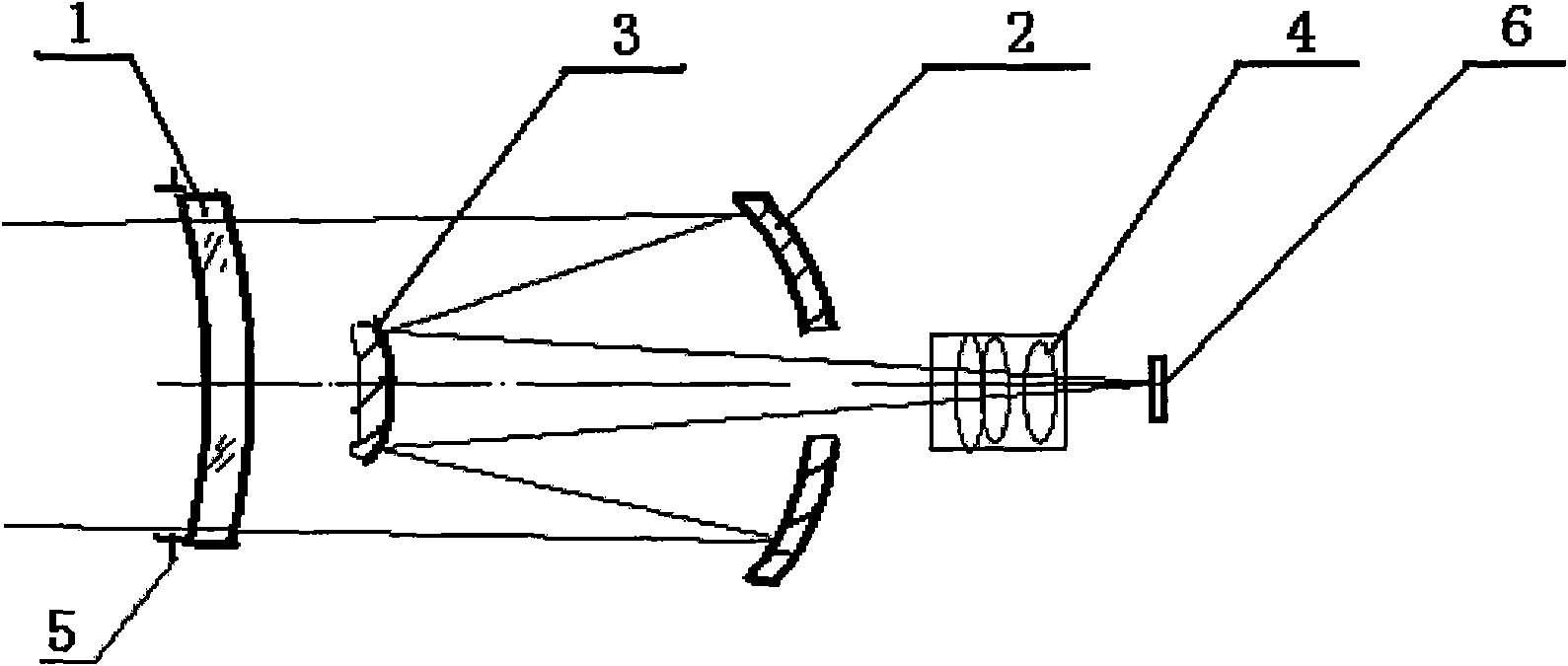
[0020] Such as figure 1 As shown, a stellar sensor imaging structure, the leftmost is the correction mirror 1, followed by the secondary mirror 3, the primary mirror 2, the correction mirror group 4, and the focal plane detector 6. The diaphragm 5 is installed on the first optical surface or the second optical surface of the correction mirror 1; a circular hole is opened in the center of the main mirror 2, and the center of the hole is located in the center of the main mirror 2, and the diameter is the smallest on the basis of its optical aperture The outer expansion is 6 mm to accommodate the correction lens group 4 to pass through the hole or to satisfy that the light from the secondary mirror 3 does not block.

[0021] The distance between the last optical surface of the correction mirror group 4 and the photosensitive surface of the focal plane detector 6 should be greater than 5 mm to meet the detector installation requirements. In this embodiment, the correction mirror g...

Embodiment 2

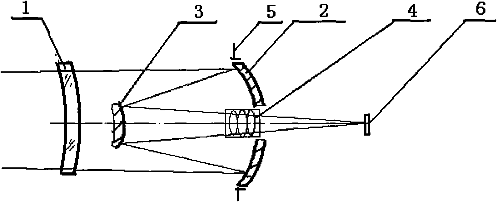
[0030] Such as figure 2 As shown, the diaphragm 5 is installed on the reflective surface of the main mirror 2, and the position of the diaphragm 5 can also be moved back and forth a small amount along the direction of the optical axis to complete the design of the present invention. The correction mirror group 4 is located at the center of the circular hole of the main mirror 2 and on the left side of the main mirror 2 .

Embodiment 3

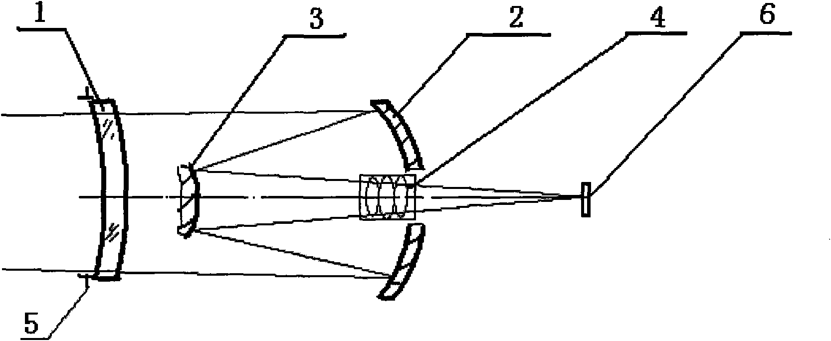
[0032] Such as image 3 As shown, the diaphragm 5 is installed on the first optical surface or the second optical surface of the aberration correcting mirror 1 , and the correcting mirror group 4 is located at the center of the circular hole of the main mirror 2 and on the left side of the main mirror 2 . The focal length f of the optical system is 500mm, and the relative aperture is The field of view is 1.6°.

[0033] The correcting mirror group 4 of the system described in this embodiment comprises 4 spherical lenses, 401, 402, 402, 404, and the lens material of the correcting mirror group 4 is glass of the same brand, such as K9, QK3, etc., and this embodiment uses K9 glass.

[0034] Its structural parameters are as follows:

[0035] Radius of curvature Center spacing Glass material

[0036] 401 First face 33.23875 4.000000 K9

[0037] 401 Second face 18.30291 2.800000

[0038] 402 First face 316.41161 4.215735 K9

[0039] 402 Second face -23.28973 16.265451

[004...


PUM


Abstract

The present invention belongs to the technical field of deep space navigation sensor, specifically discloses an imaging structure of a fixed star sensor, wherein a secondary aspheric surface is applied to an optical surface of an aberration correction lens, which not only can correct the aberration to make system imaging reach a level of near diffraction limit, but can also reduce difficulties ofsystem processing and resetting, and save cost; simultaneously the aberration correction lens can play a part in protecting a window, so as to prevent the system from the damage of space environment,such as irradiation, temperature difference, etc.

Description

technical field [0001] The invention belongs to the technical field of deep space navigation sensors, and in particular relates to a refraction-reflection star sensor imaging system. Background technique [0002] In the field of aerospace technology, the star sensor is a kind of optical sensor that determines the attitude of the spacecraft by measuring the angular position of the star in the inertial space by imaging. Stellar sensors are generally composed of optical systems, structures, detector electronic circuits, data processor electronic circuits, stray light elimination components, external interfaces, star map recognition and attitude processing software, etc. The optical system is the imaging system of the star sensor, and its imaging structure determines the superiority of the optical system. [0003] The imaging structure of the general optical system is transmissive, which is composed of multiple lens parts assembled together, such as the SED series star sensor o...

Claims


Application Information

Patent Timeline
Patent Type & Authority Applications(China)
IPC IPC(8): G02B17/08G01C21/02
Inventor 郝云彩
Owner BEIJING INST OF CONTROL ENG
Why Eureka
Try Eureka