A method for manufacturing a screen printing plate of a liquid crystal display sealing frame

A screen printing plate, liquid crystal display technology, applied in the direction of instruments, nonlinear optics, optics, etc., can solve the problems of reducing product quality, uneven box thickness, and increasing product manufacturing costs

Active Publication Date: 2016-02-03
HEBEI JIYA ELECTRONICS
View PDF5 Cites 0 Cited by
  • Summary
  • Abstract
  • Description
  • Claims
  • Application Information

AI Technical Summary

Problems solved by technology

figure 1 It is a traditional frame pattern. Because the auxiliary lines around it are straight lines, it is quite different from the pattern in the middle typesetting area. After the edge seal frame is printed on the glass substrate to be processed, it is easy to produce edge effects, which makes the substrate Different parts of the box are subjected to inconsistent forces, which leads to uneven thickness of the box, so the display often has a serious rainbow phenomenon, which greatly reduces the quality of the product
[0003] In addition, many liquid crystal display edge sealing frames are generally printed on a glass substrate. Since there is no positioning reference object on the traditional sealing frame pattern, electrodes are often cut by mistake during the division process of each liquid crystal cell. , which reduces the yield of the product and increases the manufacturing cost of the product

Method used


Image

  • A method for manufacturing a screen printing plate of a liquid crystal display sealing frame
  • A method for manufacturing a screen printing plate of a liquid crystal display sealing frame
  • A method for manufacturing a screen printing plate of a liquid crystal display sealing frame

Examples


Embodiment Construction

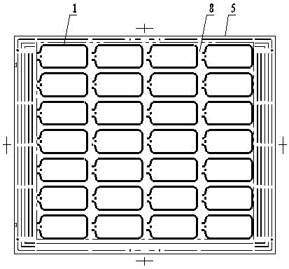
[0017] The glass substrate to be processed in the present invention refers to the entire large glass plate used in the production process of the liquid crystal display, which is generally rectangular. The display sealing frame is printed on the glass substrate to be processed, and the rectangular typesetting area refers to the area corresponding to the glass plate occupied by the product in the pattern of the screen printing plate.

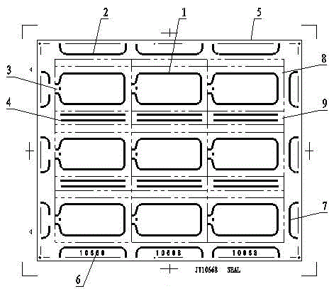
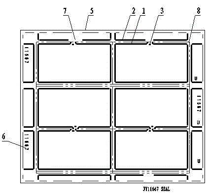
[0018] see figure 2 There are U-shaped auxiliary lines 2 around the typesetting area 8 of the screen printing plate, and there are linear auxiliary lines 4 corresponding to the small glass strips between the sealing frame patterns 1, and the seals 3 of the U-shaped auxiliary lines 2 are all facing to the left. , so the U-shaped auxiliary line 2 on the left is disconnected, which is conducive to the smooth discharge of the gas in the box. The screen printing plate does not have a sealing border pattern opposite to the sealing, so there is only th...


PUM


Abstract

The invention discloses a manufacturing method of a screen printed plate of an edge sealing frame of a liquid-crystal display, comprising the following steps: designing the patterns of the whole screen printed plate as rectangular patterns which are matched with a glass substrate to be processed; arranging a rectangular layout area for multiple patterns of the edge sealing frame on the middle parts of the rectangular patterns in a row and column form; and respectively arranging U-shaped auxiliary lines of which the opening face outwards on the two ends of the patterns of the edge sealing frame in each row and each column, wherein the U-shaped auxiliary lines are located between the outer edge of the rectangular layout area and the outer edges of the patterns of the whole screen printed plate, the whole width of each U-shaped auxiliary line is the same as the widths of the patterns of the edge sealing frames in corresponding rows or corresponding columns, and the widths of the lines of the U-shaped auxiliary line is the same as the widths of the lines of the patterns of the edge sealing frame. According to the method, the U-shaped auxiliary lines are arranged at the four sides of the layout area, the U-shaped auxiliary lines are similar to the local shapes of the patterns of the edge sealing frame, and the density of the U-shaped auxiliary lines is the same, so that the influence of the thickness uniformity of the boxes caused by edge effect is maximally eliminated, the rainbow problem caused by the influence is solved, and the quality of the product is improved.

Description

technical field [0001] The invention relates to a method for manufacturing a screen printing plate pattern used when printing an edge sealing rubber frame of a liquid crystal box by using screen printing technology, and belongs to the technical field of optical elements. Background technique [0002] The edge-sealing rubber frame of the liquid crystal display is printed by screen printing, and the quality of the edge-sealing plate directly affects the uniformity of the box thickness. figure 1 It is a traditional frame pattern. Because the auxiliary lines around it are straight lines, it is quite different from the pattern in the middle typesetting area. After the edge seal frame is printed on the glass substrate to be processed, it is easy to produce edge effects, which makes the substrate Different parts of the display are inconsistently stressed, which in turn leads to uneven thickness of the box, so the display often has a serious rainbow phenomenon, which greatly reduces...

Claims


Application Information

Patent Timeline
Patent Type & Authority Patents(China)
IPC IPC(8): G02F1/1339
Inventor 李映红王晓燕董文献
Owner HEBEI JIYA ELECTRONICS
Why Eureka
Try Eureka