
Liquid crystal display panel and array substrate thereof

A liquid crystal display panel and array substrate technology, applied in static indicators, optics, instruments, etc., can solve problems such as loss of low color shift function, abnormal color, etc.

Inactive Publication Date: 2012-10-03
SHENZHEN CHINA STAR OPTOELECTRONICS TECH CO LTD
View PDF5 Cites 41 Cited by
  • Summary
  • Abstract
  • Description
  • Claims
  • Application Information

AI Technical Summary

Problems solved by technology

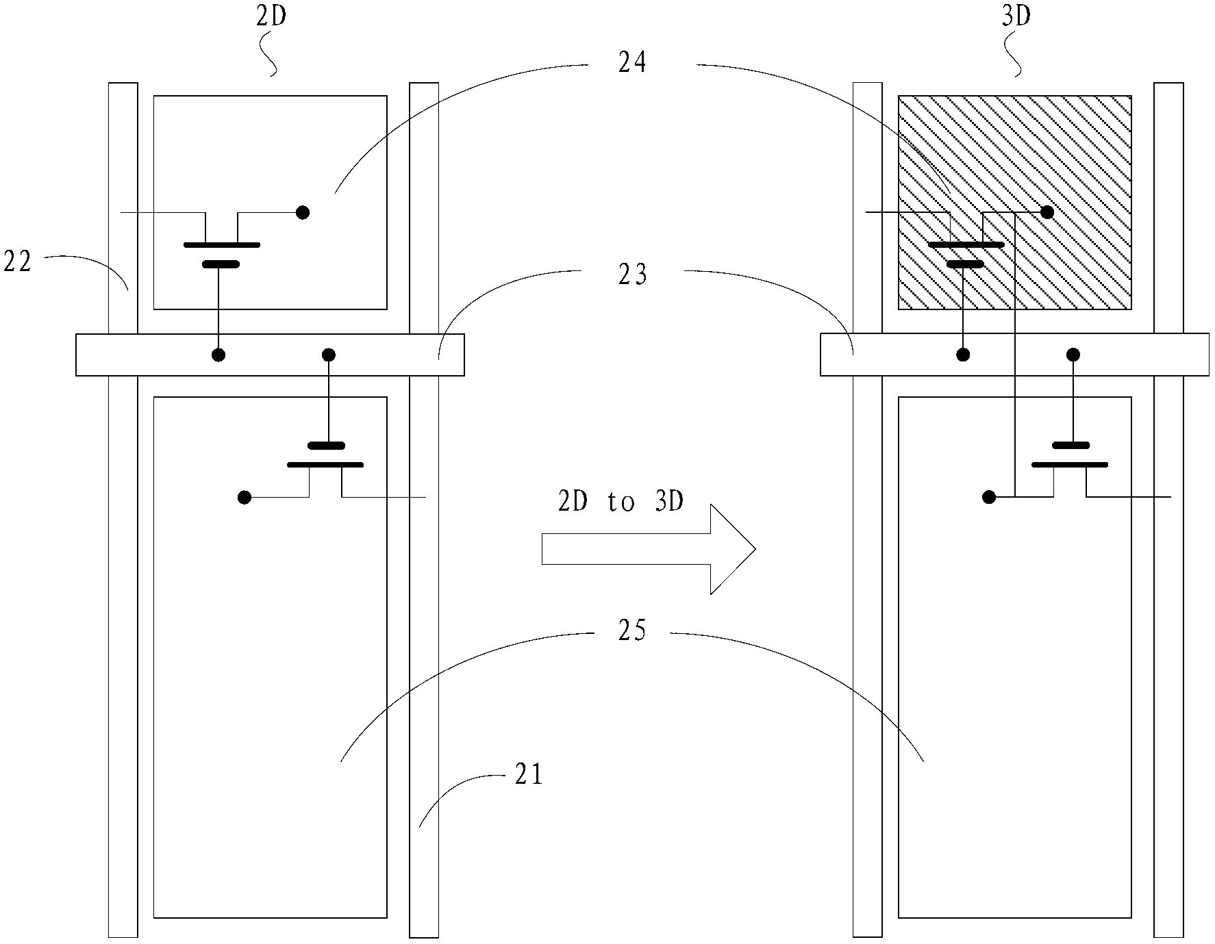
However, when switching to the 3D display mode, since the area of ​​the main pixel 24 is black, only the deflection of the liquid crystal molecules of the sub-pixel 25 is displayed, and the function of low color shift is lost. In addition, the color shift of the VA display panel itself exists , making the color anomalies observed when the viewer is at a large viewing angle position more serious

Method used


Image

  • Liquid crystal display panel and array substrate thereof
  • Liquid crystal display panel and array substrate thereof
  • Liquid crystal display panel and array substrate thereof

Examples


Embodiment Construction

[0041] The structural design of the embodiment of the array substrate of the liquid crystal display panel of the present invention enables the liquid crystal display panel to improve the color difference of large viewing angles to a certain extent in both 2D display mode and 3D display mode, reduce color distortion, and improve display effect.

[0042] The present invention will be described in detail below with reference to the drawings and embodiments.

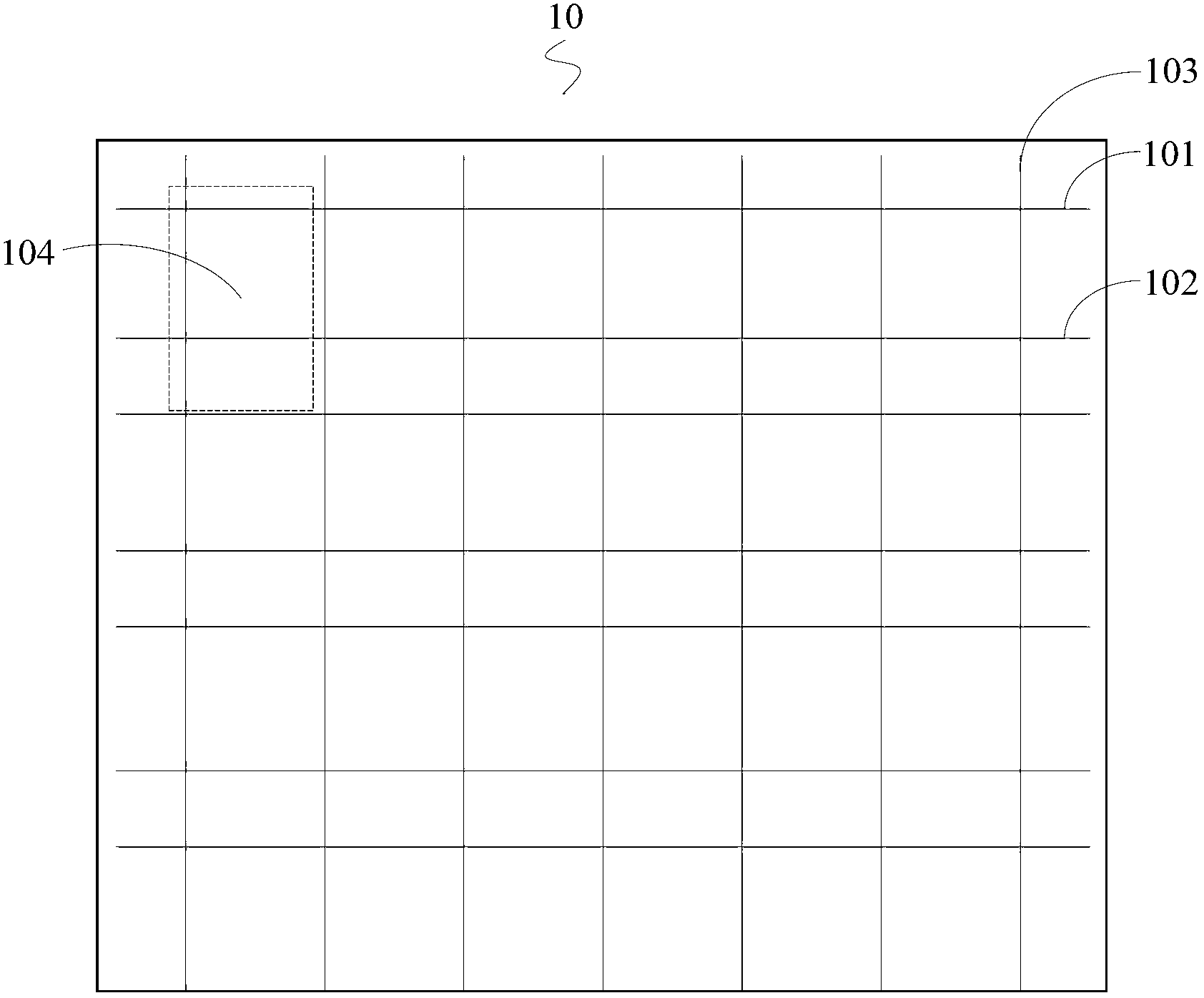
[0043] refer to image 3 with Figure 4 An embodiment of the array substrate 10 of the liquid crystal display panel of the present invention includes at least a plurality of first scan lines 101 , second scan lines 102 , data lines 103 and a plurality of pixel units 104 arranged side by side. Wherein, each pixel unit 104 includes a switch element 1041 and a pixel electrode 1042 , and each pixel unit corresponds to at least one first scan line 101 , second scan line 102 and data line 103 .

[0044] The pixel electrode 1042 ...


PUM


Abstract

The invention discloses a liquid crystal display panel and an array substrate thereof. The array substrate of the liquid crystal display panel at least comprises a plurality of first scanning lines, a plurality of second scanning lines, a plurality of data lines and a plurality of pixel units, wherein the pixel units are parallelly arranged, the pixel electrodes of the pixel units are at least separated into a first sub-electrode, a second sub-electrode and a third sub-electrode, and preset voltage difference existing when the first sub-electrode and the second sub-electrode display a voltage signal of a same image under a 3D display mode is controlled. In the invention, according to the mode, the problem of signal crosstalk of the liquid crystal display panel can be solved under the 3D display mode, thereby improving the color difference of a large viewing angle to a certain degree and reducing the color distortion.

Description

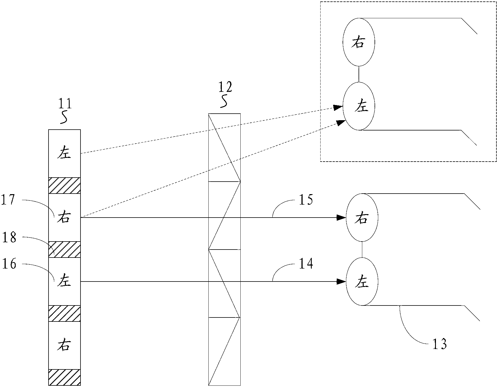
technical field [0001] The invention relates to the technical field of liquid crystal display, in particular to a liquid crystal display panel and an array substrate thereof. Background technique [0002] With continuous development of display technology, 3D (Three Dimensions, 3D) stereoscopic display technology is becoming more and more mature. 3D stereoscopic image devices such as 3D TV, 3D projection, and 3D camera emerge in an endless stream. Different from 2D (Two Dimensions, 2D) flat display, 3D stereoscopic display technology has more realistic pictures and better visual effects, and has gradually become the mainstream development direction of future display devices. [0003] FPR (Film-type Patterned Retarder, polarized) is one of the existing imaging methods of 3D liquid crystal display. Such as figure 1 As shown, the FPR 3D display system includes a liquid crystal display panel 11 , a Patterned Retarder (polarizing) film 12 and polarizing glasses 13 . The liquid...

Claims


Application Information

Patent Timeline
Patent Type & Authority Applications(China)
IPC IPC(8): G02F1/1362G02F1/1368G02F1/133G09G3/36
CPCG09G2320/0242G02F1/1368G09G2320/0209G09G2300/0447G09G3/3648G02F1/1362G09G3/36H04N13/0434G09G3/003H04N13/0452H04N13/337H04N13/356
Inventor 王醉
Owner SHENZHEN CHINA STAR OPTOELECTRONICS TECH CO LTD
Learn More