
Shuttle-type connecting clamp for zero-force electric wire

A technology for power wires and connecting clips, which is applied in the direction of conductive connection, electrical component connection, connection, etc., can solve the problems of large contact resistance of parallel grooved wire clips, many disconnection accidents, and rapid electrical erosion damage, and achieves low connection resistance. , Easy installation and low cost

Inactive Publication Date: 2014-07-30
郭金泉
View PDF6 Cites 0 Cited by
  • Summary
  • Abstract
  • Description
  • Claims
  • Application Information

AI Technical Summary

Problems solved by technology

[0002] At present, power lines, substations, and factory power distribution are not connected by force, and the commonly used parallel trench clamps have potential safety hazards such as large contact resistance, fast electric corrosion damage, burns, and disconnection accidents.
However, due to the over-tension jumper connection and branch or lead wire "T" connection of transmission lines, power distribution lines, and low-voltage lines, as well as substations and factory power distribution, there are particularly many unstressed connections. It is a weak link and a hidden danger, but it is low in cost and easy to install and disassemble, but it is still widely used

Method used


Image

  • Shuttle-type connecting clamp for zero-force electric wire
  • Shuttle-type connecting clamp for zero-force electric wire
  • Shuttle-type connecting clamp for zero-force electric wire

Examples


Embodiment Construction

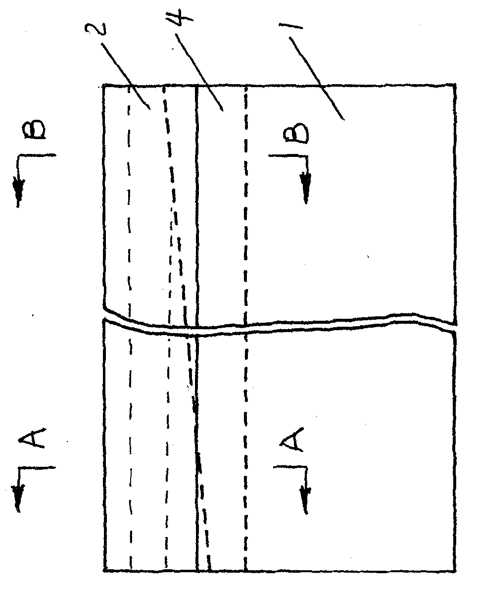
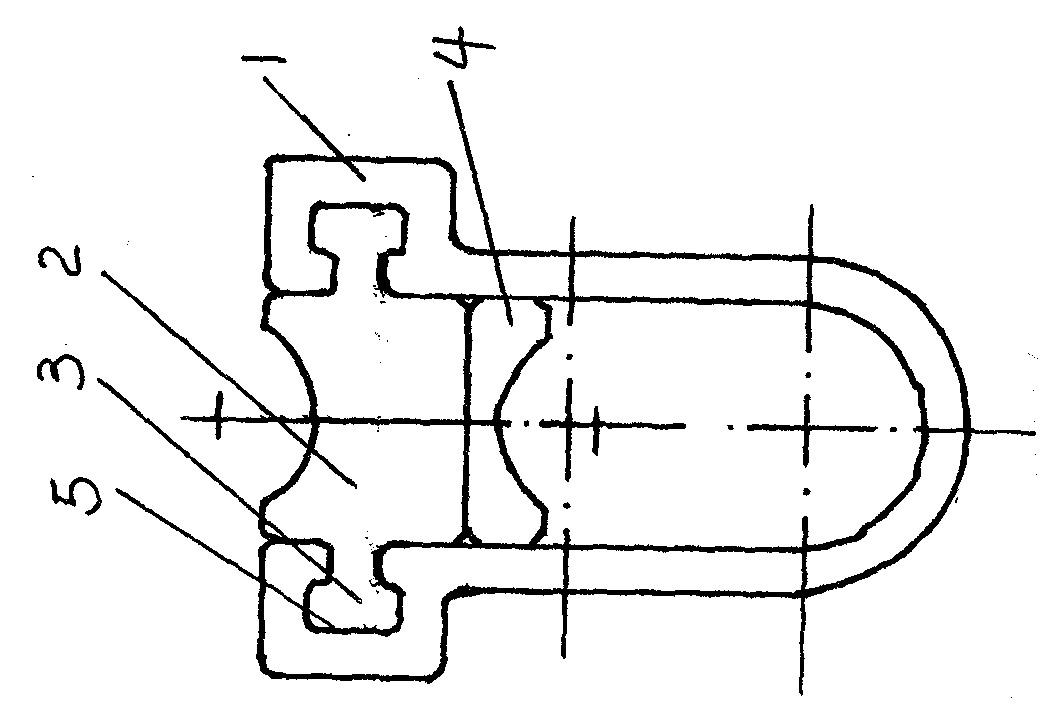
[0027] Figures 1 to 5 As shown: the shuttle-shaped connecting wire clamp for power wires without force, the wire clamp body 1 is a long wire clamp body with a "U" shape in cross section, and the left and right sides of the "U" shape on the upper mouth of the wire clamp body 1 The side clamp body is symmetrically provided with longitudinal concave groove 5, the opening of the concave groove 5 is in the cavity inside the "U"-shaped clamp body 1, the cross section of the concave groove 5 is ear-shaped, and the wire clamp body The upper opening of 1 is provided with a wedge-shaped connection insert 2 inserted longitudinally into the "U"-shaped wire clip body, and the inserts on the left and right sides of the wedge-shaped connection insert 2 are symmetrically provided with longitudinal convex ribs 3, convex ribs 3 and concave Corresponding to the groove 5, the convex rib 3 is inserted into the concave groove 5 and the cross section of the convex rib 3 matches the cross section of...


PUM


Abstract

The invention discloses a shuttle-type connecting clamp for a zero-force electric wire. The connecting clamp comprises a long clamp body with a U-shaped cross section, longitudinal grooves with ear-shaped cross sections are symmetrically arranged on the left and right sides of the upper opening of the clamp body, a wedge-shaped connecting inserted block which is inserted into the U-shaped clamp body longitudinally is arranged on the upper opening of the clamp body, longitudinal ribs are symmetrically arranged on inserted block bodies of the left and right sides of the wedge-shaped connecting inserted block and inserted into the grooves, the cross sections of the ribs match with the cross sections of the grooves, and a connecting inserted block inserted into the U-shaped clamp body longitudinally is arranged in the inner cavity of the U-shaped clamp body under the wedge-shaped connecting inserted block. The connecting clamp has the advantages of being safe and reliable in use, good in connecting effect, convenient to operate and low in using cost.

Description

technical field [0001] The invention relates to a connection clamp for power wires, which is used for the non-stressed connection of power wires, and is especially suitable for tension-resistant over-leading connections of power transmission lines, power distribution lines, and low-voltage lines, as well as "T" connection of branches or lead wires, and Substation, factory distribution power conductor connection. Background technique [0002] At present, power lines, substations, and factory power distribution are not connected by force, and the commonly used parallel trench clamps have potential safety hazards such as large contact resistance, fast electrical erosion, burns, and disconnection accidents. However, due to the over-tension jumper connection and branch or lead wire "T" connection of transmission lines, power distribution lines, and low-voltage lines, as well as substations and factory power distribution, there are particularly many unstressed connections. It is ...

Claims


Application Information

Patent Timeline
Patent Type & Authority Patents(China)
IPC IPC(8): H01R11/14H01R4/50
Inventor 郭金泉
Owner 郭金泉
Learn More