Improved voice coil motor

A voice coil motor, an improved technology, applied in the direction of electrical components, electromechanical devices, etc., can solve the problems of easy deformation, waste products, and weak strength of upper shrapnel, and achieve the effects of not being easy to deform permanently, reducing manufacturing costs, and improving yield

Active Publication Date: 2012-10-03
JINLONG MACHINERY & ELECTRONICS CO LTD
View PDF4 Cites 4 Cited by
  • Summary
  • Abstract
  • Description
  • Claims
  • Application Information

AI Technical Summary

Problems solved by technology

In order to reduce the occupied area, this kind of upper shrapnel does not have an outer ring area outside the elastic arm area, that is, there are gaps (17) between the fixed areas, which are not connected to each other, so the strength of this kind of upper shrapnel is very weak and extremely It is easy to deform. During the installation operation, if the force is slightly deviated, it will cause permanent deformation in the fixed area and the elastic arm area, which will affect the control accuracy of the final voice coil motor and cause waste products.

Method used


Image

  • Improved voice coil motor
  • Improved voice coil motor
  • Improved voice coil motor

Examples


Embodiment 1

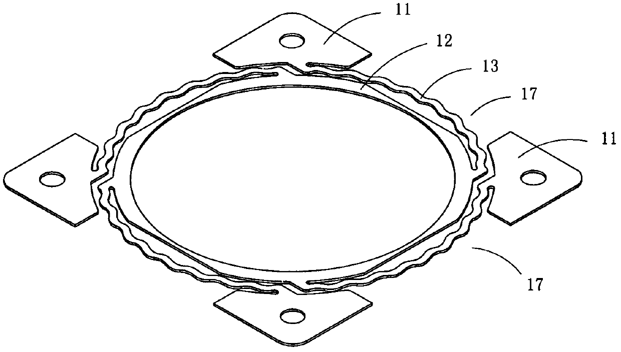
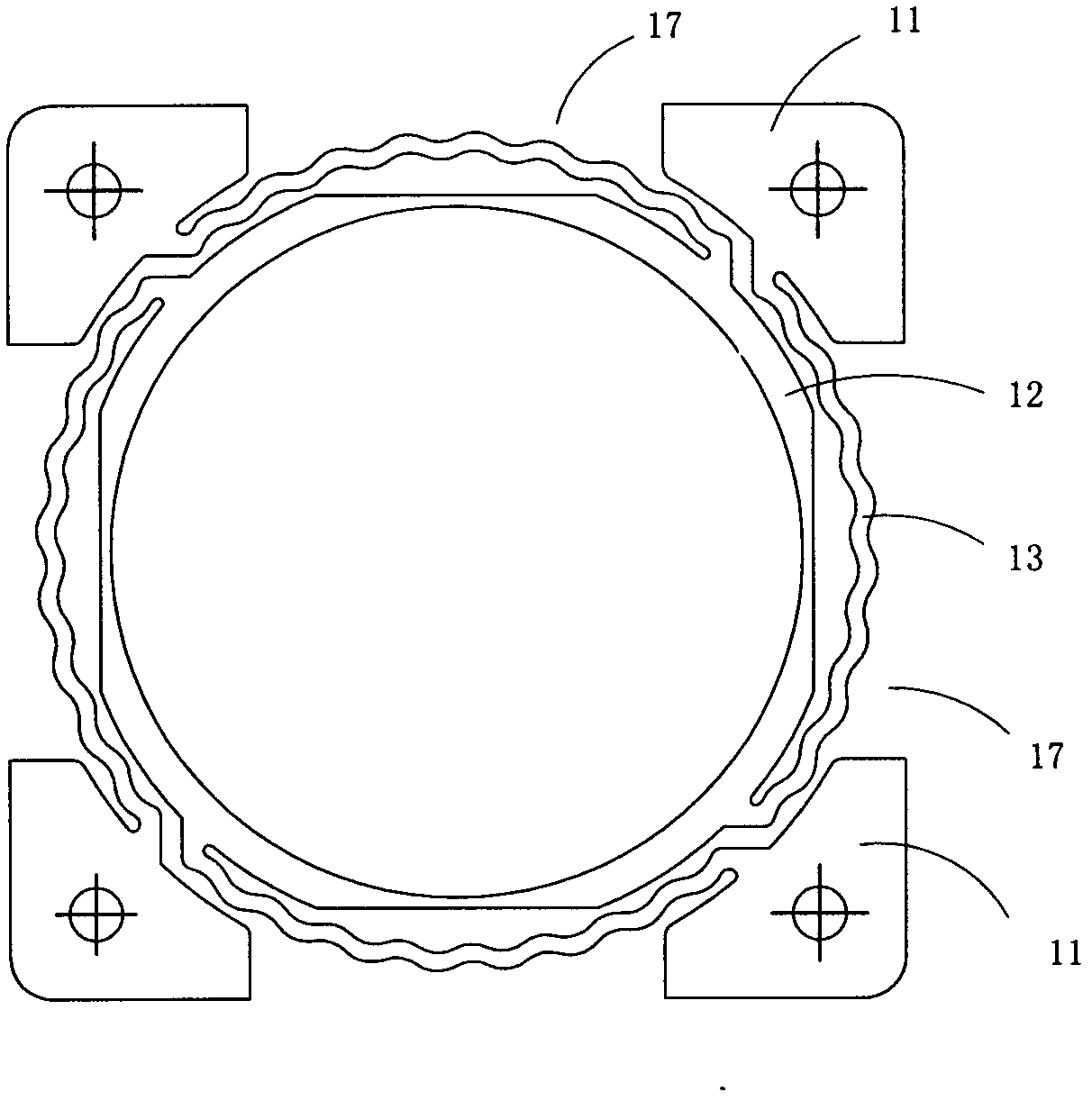
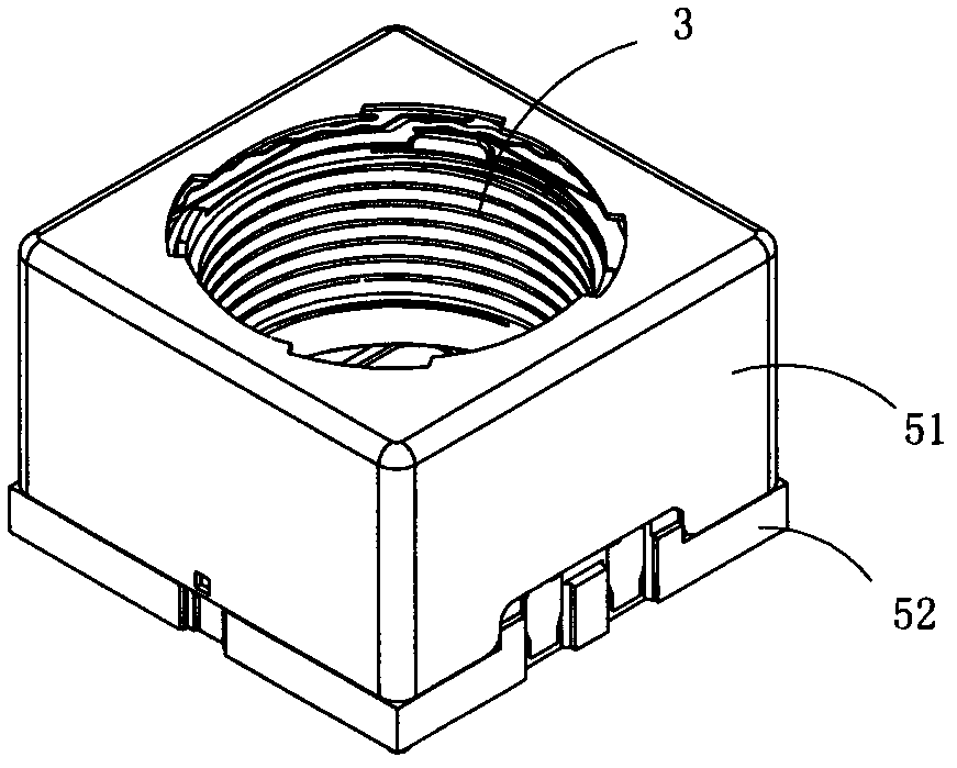
[0026] Figure 3 to Figure 6 A first embodiment of the invention is shown, in which image 3 It is a schematic diagram of a three-dimensional structure of the first structure of the present invention; Figure 4 yes image 3 An exploded diagram of the improved voice coil motor shown; Figure 5 yes image 3 A schematic diagram of the three-dimensional structure of the upper shrapnel in the improved voice coil motor shown; Image 6 yes Figure 5 A front view of the upper shrapnel shown.

[0027] This embodiment is an improved voice coil motor, see Figure 3 to Figure 6 , including an upper elastic piece 1, an upper elastic piece mounting frame 2, a lens carrier 3, a lower elastic piece 55, an upper cover 51, a base 52, a magnet assembly 53 and a coil 54; the base 52 and the upper cover 51 form a housing, and the lens The carrier 3 is arranged between the upper elastic piece 1 and the lower elastic piece 55, the magnet assembly 53 includes four rectangular magnets made of p...

Embodiment 2

[0037] Figure 7 with Figure 8 A second embodiment of the invention is shown, in which Figure 7 It is a schematic diagram of a three-dimensional structure of the upper elastic piece in the second structure of the present invention; Figure 8 yes Figure 7 A front view of the upper shrapnel shown.

[0038] This embodiment is basically the same as Embodiment 1, the difference is: see Figure 7 with Figure 8 As shown, in this embodiment, a connecting plate 18 is provided between two adjacent fixing areas 11 , and the connecting plate 18 and the fixing areas 11 are located on the same plane. The reinforcing plates 14 are located at the peripheral edges of each fixing area 11 and each connecting plate 18 . The connection plate 18 improves the overall strength of the upper elastic piece 1 to a certain extent, but because the upper elastic piece 1 is very thin, the strength improvement is still very limited, and the overall strength must be improved as much as possible by th...


PUM


Abstract

The invention discloses an improved voice coil motor. The improved voice coil motor comprises an upper spring plate, an upper spring plate mounting rack and a lens carrier, wherein a plurality of supporting legs are arranged on the upper spring plate mounting rack; the upper spring plate is fixed on the supporting legs; the upper spring plate comprises fixed regions, an inner ring region and a plurality of elastic arm regions; the fixed regions are fixedly arranged on the supporting legs; the inner ring region is fixed on the lens carrier; the elastic arm regions connect the fixed regions and the inner ring region; the upper spring plate also comprises reinforcement plates connecting two adjacent fixed regions; and each reinforcement plate is vertical to the plane where the fixed regions are located. The improved voice coil motor has the following positive effects: the upper spring plate comprises the reinforcement plates connecting two adjacent fixed regions and each reinforcement plate is vertical to the plane where the fixed regions are located; therefore, the reinforcement plates can effectively improve the strength of the upper spring plate on the basis that the floor area is not increased, so that the upper spring plate is not liable to deform permanently during mounting and operation and the yield is effectively improved, thus reducing the manufacture cost to some extent.

Description

technical field [0001] The invention relates to an improved voice coil motor, in particular to an improved voice coil motor applied to cameras, video cameras or mobile phones with camera functions to drive the lens to move to adjust the focal length. Background technique [0002] A traditional voice coil motor includes an upper elastic piece, an upper elastic piece mounting frame and a lens carrier. The upper elastic piece mounting frame is provided with a plurality of supporting feet, and the upper elastic piece is fixed on the supporting feet. [0003] figure 1 It is a schematic diagram of the three-dimensional structure of the upper shrapnel in a traditional voice coil motor. figure 2 yes figure 1 A front view of the upper elastic sheet shown; this upper elastic sheet includes a fixed area (11) fixedly arranged on the support foot, an inner ring area (12) fixed on the lens carrier, and a fixed area (11) connected to the fixed area (11) ) and a plurality of elastic arm...

Claims


Application Information

Patent Timeline
IPC IPC(8): H02K33/00H02K33/18
Inventor 金绍平方绍斌夏太红金士雷黄晓敏颜石磊
Owner JINLONG MACHINERY & ELECTRONICS CO LTD
Why Eureka
Try Eureka