Short-circuit protection method for self-excitation push-pull type convertor

A self-excited push-pull and short-circuit protection technology, applied in the direction of output power conversion devices, electrical components, etc., can solve problems such as failure to output normal voltage, failure to start normally, and poor capacitive load capacity at the output end.

Active Publication Date: 2014-07-23
金升阳(怀化)科技有限公司
View PDF6 Cites 2 Cited by
  • Summary
  • Abstract
  • Description
  • Claims
  • Application Information

AI Technical Summary

Problems solved by technology

[0009] 1. Poor capacitive load capacity at the output end
by figure 1 For example, when the value of the capacitor C3 is too large, when the power supply of the converter is powered on, since the terminal voltage of the capacitor C3 is 0, the capacitor C3 is equivalent to a short circuit when the power is turned on, and the circuit works under the high-frequency self-excited push-pull oscillation , at this time, the transmission efficiency of transformer B1 is low, and it is impossible to charge the capacitor C3 with a large current, which makes it difficult to start the circuit, and it takes a long time for the output terminal DC out to output the normal voltage. Low voltage output, unable to output normal voltage
For example, the circuit parameters in the above three patent publications are made into a DC converter with an input of 5V and an output of 5V. When the capacitor C3 is increased to 220uF, it cannot be started normally.
[0010] 2. The short-circuit protection function and the capacitive load capacity are not well balanced
[0014] 3. In order to obtain a good short-circuit protection function and a large capacitive load capacity, it is necessary to add a large number of other components, generally including optocouplers and operational amplifiers for voltage detection, which are costly and difficult to make small

Method used


Image

  • Short-circuit protection method for self-excitation push-pull type convertor
  • Short-circuit protection method for self-excitation push-pull type convertor
  • Short-circuit protection method for self-excitation push-pull type convertor

Examples


Embodiment 1

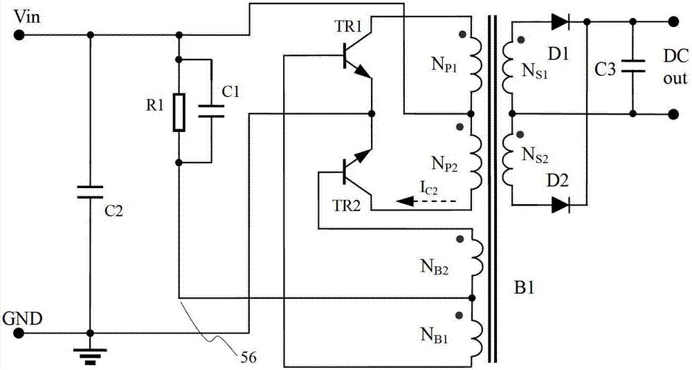
[0062] Embodiment one adopts and figure 1 The same circuit topology is made into a converter with input DC 5V, output DC 5V, and output current of 200mA, that is, the output power is 1W.

[0063] In order to illustrate the effect of Embodiment 1, the self-excited push-pull converter of the prior art used for comparison adopts the same circuit parameters: it includes a transformer B1, and the transformer B1 is composed of a magnetic core and a corresponding coil winding, and the coil winding includes a primary power winding N P1 and N P2 , primary side feedback winding N B1 and N B2 , secondary output winding N S1 and N S2 ; The magnetic core adopts outer diameter of 5.1mm, inner diameter of 2.3mm, and height of 1.7mm, and the material adopts TPW33 magnetic material of Tiantong Holding Co., Ltd. Resistor R1 is 1KΩ; capacitor C2 and capacitor C3 are chip capacitors of 2.2uF / 10V, starting capacitor C1 is a chip capacitor of 0.047uF / 10V; triode TR1 and triode TR2 are switchi...

Embodiment 2

[0084] The prior art self-excited push-pull converter in Embodiment 1 is optimized by adopting the complete method of the present invention:

[0085] Step A, artificially short-circuit the output terminal, adjust the leakage inductance of the transformer, and ensure that the short-circuit protection current at this time is larger than the short-circuit protection limit current; at this time, it is adjusted from 90mA to about 300mA. This current increases rapidly with time, so when adjusting, control The working time of the circuit after power-on;

[0086] Step A1, add a capacitor between the collectors of the two push-pull transistors in the self-excited push-pull converter, and adjust its capacity. It is convenient to debug here, and the variable capacitor 7 / 270pF used in the medium-wave radio is used. , commonly known as double-connection, the capacity can be changed by rotating the handle, so that when an artificial short circuit occurs at the output end, the short-circuit ...

Embodiment 3

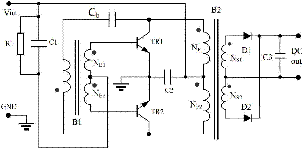
[0095] The third embodiment adopts Figure 9 shows the Royer circuit, with figure 1 The difference is that one end of the starting capacitor C1 is still connected to the center tap of the feedback winding of the self-excited push-pull converter, and the other end is connected to the negative power supply (power ground). The measured performance of the self-excited push-pull converter is exactly the same as the parameters shown in Table 1, and the numerical error is within 3%.

[0096] Using the method of the present invention to optimize the prior art self-excited push-pull converter in Embodiment 3, the steps are as follows:

[0097] Step A, short-circuit the output terminal, and adjust the leakage inductance of transformer B1 to ensure that the short-circuit protection current at this time is greater than the short-circuit protection limit current; at this time, the short-circuit protection current is adjusted from 90mA to about 300mA. This current increases rapidly with ti...


PUM


Abstract

The invention discloses a short-circuit protection method for a self-excitation push-pull type convertor. The short-circuit protection method mainly comprises the following steps of: shorting out the output end of the self-excitation push-pull type convertor, and adjusting leakage inductance of a main power transformer in the self-excitation push-pull type convertor, so that short-circuit protection current of the self-excitation push-pull type convertor is more than short-circuit protection limited current; increasing an electric capacity of a starting capacitor in the self-excitation push-pull type convertor, so that the self-excitation push-pull type convertor enters an interval type high-frequency oscillatory condition, and the short-circuit protection current is reduced to be lower than the short-circuit protection limited current. With the adoption of the short-circuit protection method, the self-excitation push-pull type convertor can carry a large-capacity load on the premise of not additionally arranging an element. Furthermore, when the circuit is shorted out, the short-circuit protection current is still very low so that the self-excitation push-pull type convertor can work at an output short-circuit state for a long period.

Description

technical field [0001] The invention relates to a short-circuit protection method for a power converter, in particular to a short-circuit protection method for a self-excited push-pull converter. Background technique [0002] The existing self-excited push-pull converter, the circuit structure comes from the self-excited oscillating push-pull transistor single-transformer DC converter invented by G.H.Royer in 1955, which is also the beginning of realizing high-frequency conversion control circuit; some circuits From the self-excited push-pull double transformer circuit invented by Jen Sen in the United States in 1957, it was later called the self-oscillating Jensen circuit; these two circuits are collectively referred to as the self-excited push-pull circuit pull converter. The self-excited push-pull converter is described on pages 67 to 70 of "The Principle and Design of Switching Power Supply" published by Electronics Industry Press, and the book's ISBN number is 7-121-00...

Claims


Application Information

Patent Timeline
Patent Type & Authority Patents(China)
IPC IPC(8): H02M1/32
Inventor 王保均
Owner 金升阳(怀化)科技有限公司
Why Eureka
Try Eureka