Current equalization circuit for multi-module shunt-wound power supply
What is Al technical title?
Al technical title is built by PatSnap Al team. It summarizes the technical point description of the patent document.
A multi-module, parallel technology, which is applied in the direction of electrical components, electric variable adjustment, output power conversion devices, etc., can solve the problems of poor accuracy and low reliability, and achieve improved reliability, high current sharing accuracy, and increased redundancy The effect of the design
Inactive Publication Date: 2012-10-03
BEIJING MECHANICAL EQUIP INST
View PDF3 Cites 7 Cited by
Summary
Abstract
Description
Claims
Application Information
AI Technical Summary
This helps you quickly interpret patents by identifying the three key elements:
Problems solved by technology
Method used
Benefits of technology
Problems solved by technology
[0004] The purpose of the present invention is to provide a current equalizing circuit for multi-module parallel power supply, which solves the problems of poor accuracy and low reliability of the current equalizing circuit of high-power power supply
Method used
Image
Click on the blue label to locate the original text in one second.
Reading with bidirectional positioning of images and text.
Examples
Embodiment Construction
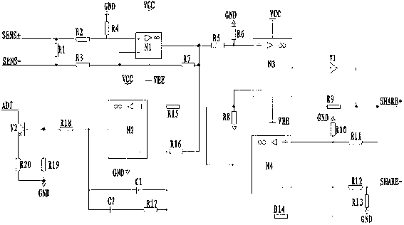
[0010] A current sharing circuit for multi-module parallel power supply, comprising: sampling resistor R1, operational amplifier N1, voltage dividing resistor R2, voltage dividing resistor R3, voltage dividing resistor R4, feedback resistor R7, operational amplifier N3, voltage dividing resistor R5 , voltage divider resistor R6, voltage divider resistor R8, feedback resistor R9, operational amplifier N2, voltage divider resistor R15, voltage divider resistor R16, feedback capacitor C1, feedback resistor R17, feedback capacitor C2, adjustment transistor V2, drive resistor R18, divider The piezoresistor R19 and the adjusting resistor R20 also include: a diode V1, an operational amplifier N4, a voltage dividing resistor R10, a voltage dividing resistor R11, a voltage dividing resistor R12, a grounding resistor R13, and a feedback resistor R14.
[0011] The two ends of the sampling resistor R1 are respectively connected to the SENS+ terminal and the SENS- terminal of the output cur...
PUM
Abstract
The invention discloses a current equalization circuit for a multi-module shunt-wound power supply. The current equalization circuit comprises a sampling resistor R1, an operational amplifier N1 and a divider resistor R2, and further comprises a diode V1, an operational amplifier N4, a divider resistor R10, a divider resistor R11, a divider resistor R12, a grounding resistor R13 and a feedback resistor R14, wherein one end of a divider resistor R4 is connected with the positive input terminal of the operational amplifier N1, and other end of the divider resistor R4 is grounded. When the current equalization circuit works, the module with the maximum output current, in a plurality of shunt-wound modules, automatically serves as a main module, and other modules are slave modules; voltage errors of all the modules are sequentially regulated to correct unbalanced current distribution of a load; when the gross power of a system has a larger margin in comparison with the load, the failure of a single module can not influence the normal operation of the shunt-wound power supply; and as a redundant design of the shunt-wound power supply is added, the product reliability is effectively improved.
Description
technical field [0001] The invention relates to a current equalizing circuit, in particular to a current equalizing circuit for multi-module parallel power supply. Background technique [0002] At present, the general current sharing circuit of parallel power supply is an average current sharing circuit, including: sampling resistor R1, operational amplifier N1, voltage dividing resistor R2, voltage dividing resistor R3, voltage dividing resistor R4, feedback resistor R7, operational amplifier N3, average resistor R21 , voltage dividing resistor R5, voltage dividing resistor R6, voltage dividing resistor R8, feedback resistor R9, operational amplifier N2, voltage dividing resistor R15, voltage dividing resistor R16, feedback capacitor C1, feedback resistor R17, feedback capacitor C2, adjustment transistor V2, Driving resistor R18, voltage dividing resistor R19, and adjusting resistor R20. [0003] The average current automatic current sharing circuit can automatically reali...
Claims
Application Information
Patent Timeline
Application Date:The date an application was filed.
Publication Date:The date a patent or application was officially published.
First Publication Date:The earliest publication date of a patent with the same application number.
Issue Date:Publication date of the patent grant document.
PCT Entry Date:The Entry date of PCT National Phase.
Estimated Expiry Date:The statutory expiry date of a patent right according to the Patent Law, and it is the longest term of protection that the patent right can achieve without the termination of the patent right due to other reasons(Term extension factor has been taken into account ).
Invalid Date:Actual expiry date is based on effective date or publication date of legal transaction data of invalid patent.