
RFID loop antenna matching method and antenna, electronic tag, reader

A technology of a loop antenna and a matching method, applied in the field of communication, can solve the problems such as the inability to increase the number of antenna turns, the inability to apply the antenna, and the poor non-contact performance.

Active Publication Date: 2015-10-07
BEIJING WATCH DATA SYST
View PDF6 Cites 0 Cited by
  • Summary
  • Abstract
  • Description
  • Claims
  • Application Information

AI Technical Summary

Problems solved by technology

In this way, due to the limited internal space of the mobile phone, the size of the absorbing material cannot be enlarged and thickened infinitely, so the impact of the battery can only be improved to a certain extent;
[0008] 2. Increase the inductance of the antenna by increasing the number of antenna turns with appropriate absorbing materials, but in this way, in order to ensure the normal realization of the non-contact function, that is, the resonant frequency is within a certain range, not infinite increase the number of antenna turns, nor can one antenna be applied to all mobile phones;
Therefore, if the traditional antenna form is placed in different mobile phone terminals, the overall resonant frequency will be different, and it is difficult to ensure that the resonant frequency works within the optimal operating frequency range, resulting in poor non-contact performance in actual use.

Method used


Image

  • RFID loop antenna matching method and antenna, electronic tag, reader
  • RFID loop antenna matching method and antenna, electronic tag, reader
  • RFID loop antenna matching method and antenna, electronic tag, reader

Examples


Embodiment Construction

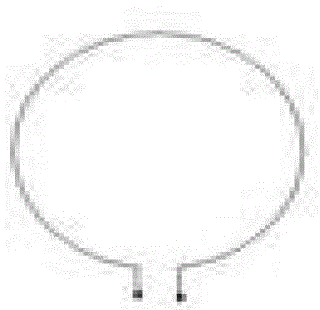
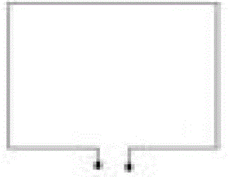
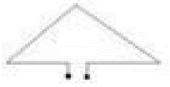
[0034] Embodiments of the present invention provide a matching method for an RFID loop antenna, an antenna, an electronic tag, and a reader. In the RFID loop antenna, a variable capacitor connected between two terminals of the antenna coil is added, and the variable capacitor is connected when needed. The capacitance is adjusted to a suitable value so that the operating frequency of the antenna is the same as or the closest to the set frequency, wherein the set frequency refers to the required operating frequency of the antenna. In the embodiment of the present invention, the frequency of the excitation signal (also called the excitation frequency) The value is the same as the set frequency, so that the capacitance parameter can be changed according to the actual environment of the RFID loop antenna to obtain a better resonance frequency.

[0035] like Figure 5 As shown, the RFID loop antenna matching method provided in the embodiment of the present invention includes:

[00...


PUM


Abstract

The invention discloses a radio frequency identification (RFID) loop antenna matching method, an antenna, an electronic tag and a reader and relates to the communication technology. A variable capacitor connected between two terminals of an antenna coil is added in the RFID loop antenna, and can be adjusted to be with appropriate valve when needed so as to lead the working frequency of the antenna to be identical to or close to the set frequency. Therefore, capacitance parameters can be changed according to the actual environment of the RFID loop antenna, and good resonant frequency can be obtained.

Description

technical field [0001] The invention relates to communication technology, in particular to an RFID loop antenna matching method, an antenna, an electronic tag and a reader. Background technique [0002] RFID (Radio Frequency Identification, radio frequency identification) is a non-contact automatic identification, which automatically identifies the target object and obtains relevant data through radio frequency signals, and the identification work does not require manual intervention. RFID is a simple wireless system consisting of an interrogator (or reader) and many transponders (or electronic tags). [0003] With the continuous improvement of RFID technology, the application field of RFID has been continuously expanded. Among them, 13.56MHz RFID has also been developed rapidly, and a new application field - mobile payment has emerged. The current mobile payment forms are mainly divided into the following two types: off-site non-real-time payment is a commonly used payment...

Claims


Application Information

Patent Timeline
Patent Type & Authority Patents(China)
IPC IPC(8): H04B5/00H01Q7/00H01Q1/22G06K19/077G06K7/00
Inventor 刘利家韩静张雁陈毅平王立峰
Owner BEIJING WATCH DATA SYST
Learn More