
A frequency locking method and system for a magnetic resonance wireless charging system

A technology of frequency locking and wireless charging, applied to electrical components, circuit devices, etc., can solve problems such as complex circuits at the transmitting end and difficulty in frequency locking, and achieve the effects of simplified docking mechanism, simple frequency matching, and improved compatibility

Inactive Publication Date: 2018-01-30
SHANGHAI AMPHENOL AIRWAVE COMM ELECTRONICS CO LTD
View PDF4 Cites 0 Cited by
  • Summary
  • Abstract
  • Description
  • Claims
  • Application Information

AI Technical Summary

Problems solved by technology

[0006] The purpose of the present invention is to provide a frequency locking method and system for a magnetic resonance wireless charging system to solve the problem of difficult frequency locking in the existing magnetic resonance wireless charging system
[0007] The second object of the present invention is to provide a frequency locking method and system for a magnetic resonance wireless charging system to solve the problem of complex transmitter circuits in the existing magnetic resonance wireless charging system

Method used


Image

  • A frequency locking method and system for a magnetic resonance wireless charging system
  • A frequency locking method and system for a magnetic resonance wireless charging system
  • A frequency locking method and system for a magnetic resonance wireless charging system

Examples


Embodiment 1

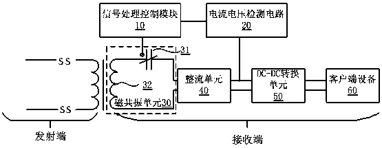
[0035] The composition diagram of the frequency locking system of the magnetic resonance wireless charging system in this embodiment is as follows figure 2 As shown, the frequency locking system is set at the receiving end of the magnetic resonance wireless charging system, and the frequency locking system includes a signal processing control module 10, a current and voltage detection circuit 20, a magnetic resonance unit 30, a rectification unit 40, and a DC-DC conversion unit 50 and the client device 60 to be charged.

[0036] The adjustable capacitor 31 is connected in series with the magnetic resonance coil 32 at the receiving end to form a magnetic resonance unit 30, the magnetic resonance unit 30 is connected to the rectification unit 40, the rectification unit 40 is connected to the DC-DC conversion unit 50, and the DC-DC conversion unit 50 is connected to the The client device 60 is connected. When the system is charging, the magnetic resonance unit 30 first receives...

Embodiment 2

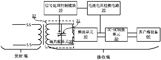
[0058] A frequency locking system for a magnetic resonance wireless charging system provided in this embodiment is as follows: image 3 As shown, the frequency locking system is set at the receiving end of the magnetic resonance wireless charging system, and the frequency locking system includes a signal processing control module 10, a current and voltage detection circuit 20, a magnetic resonance unit 30, a rectifier unit 40, and a DC-DC conversion unit 50. and the client device 60 to be charged.

[0059] The magnetic resonance unit 30 includes a parallel adjustable capacitor 31 and a magnetic resonance coil 32 at the receiving end. The magnetic resonance unit 30 is connected to the rectification unit 40, the rectification unit 40 is connected to the DC-DC conversion unit 50, and the DC-DC conversion unit 50 is connected to the customer The end device 60 is connected.

[0060] The signal processing control module 10 is coupled with the adjustable capacitor 31 to adjust the v...

Embodiment 3

[0064] A frequency locking system for a magnetic resonance wireless charging system provided in this embodiment is as follows: Figure 4 As shown, the frequency locking system is set at the receiving end of the magnetic resonance wireless charging system, and the frequency locking system includes a signal processing control module 10, a current and voltage detection circuit 20, a magnetic resonance unit 30, a rectifier unit 40, and a DC-DC conversion unit 50. and the client device 60 to be charged, the filtering unit 70 and the second rectifying unit 80 .

[0065] The magnetic resonance unit 30 includes an adjustable capacitor 31 connected in series and a magnetic resonance coil 32 at the receiving end. The magnetic resonance unit 30 is connected to the rectification unit 40, the rectification unit 40 is connected to the DC-DC conversion unit 50, and the DC-DC conversion unit 50 is connected to the customer The terminal device 60 is connected; the filter unit 70 is current-cou...


PUM


Abstract

The frequency locking method and system for the magnetic resonance wireless charging system provided by the present invention realizes the frequency alignment of the magnetic resonance wireless charging transmitting end and receiving end through another method different from the traditional method. When adjusting the method, the voltage value of the adjustable capacitor is adjusted in steps of ΔV, and the adjustment is continued according to the current or voltage change in the coil caused by the change of the resonance frequency. When the current or voltage becomes larger, the adjustment is continued, and vice versa. Adjust, and judge that the system has obtained the best resonant frequency according to the difference between the two current or voltage changes, and lock the frequency to complete the frequency lock. That is to say, the present invention generates and adjusts the resonant frequency of the magnetic resonance unit (LC circuit) by setting an adjustable capacitor at the receiving end, which not only realizes one-to-many wireless charging, but also simplifies the docking mechanism between the transmitting end and the receiving end, improving both The compatibility between them reduces the complexity of the transmitter circuit, and the method is easy to implement and convenient to control.

Description

technical field [0001] The invention relates to the technical field of wireless charging, in particular to a frequency locking method and system for a magnetic resonance wireless charging system. Background technique [0002] With the gradual entry of various electronic products into people's lives, especially the increasing functions of notebook computers, tablet computers, and smart phones, people generally feel that the existing battery capacity can no longer meet their growing entertainment and work needs, and the home is full of The various power connectors and power cords everywhere are also a headache, so the desire to realize on-the-go charging through wireless charging, that is, charging and entertainment that do not conflict with each other, is also becoming stronger and stronger. [0003] At present, there are several wireless charging methods: electric field coupling method, electromagnetic induction method, magnetic coupling method, and radio wave method. Among ...

Claims


Application Information

Patent Timeline
Patent Type & Authority Patents(China)
IPC IPC(8): H02J50/12H02J5/00
Inventor 何大伟
Owner SHANGHAI AMPHENOL AIRWAVE COMM ELECTRONICS CO LTD
Learn More