Sonic toothbrush vibration structure for effectively reducing vibration of handle

A handle and sound wave technology, used in dentistry, cleaning teeth, medical science, etc., can solve the problems of increasing body vibration and easy damage, and achieve the effect of reducing handle vibration

Inactive Publication Date: 2012-10-10
NINGBO SEAGO ELECTRIC
View PDF4 Cites 7 Cited by
  • Summary
  • Abstract
  • Description
  • Claims
  • Application Information

AI Technical Summary

Problems solved by technology

[0002] Toothbrush is the most commonly used tool for cleaning teeth. It is used to remove bacteria, tartar and small debris attached to the teeth. It can prevent periodontal diseases and protect people's oral hygiene and dental health. Toothbrushes on the market now Variety, different structures, such as Chinese patent, patent number: ZL200620102401.9 discloses a kind of sonic vibration toothbrush, including the brush head with bristles, the brush neck rod and the vibration part double as the brush handle, the vibration part is provided with vibration The joint is connected to the brush neck rod through the vibration joint, and other components such as the vibration source motor, the vibration rod and the main body electric board are all arranged in the handle that doubles as the vibration part. The main defect of this toothbrush is that the vibration source and the main body control board are arranged in the Together, it is easily damaged under high-frequency vibration, and the handle doubles as the vibration part to increase the vibration of the body, so the desired effect cannot be achieved

Method used


Image

  • Sonic toothbrush vibration structure for effectively reducing vibration of handle
  • Sonic toothbrush vibration structure for effectively reducing vibration of handle
  • Sonic toothbrush vibration structure for effectively reducing vibration of handle

Examples


Embodiment Construction

[0024] The present invention will be further described in detail below in conjunction with the specific embodiments of the accompanying drawings.

[0025] Figure 1 to Figure 9 It is a schematic diagram of the structure of the present invention.

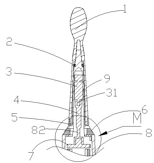
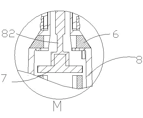
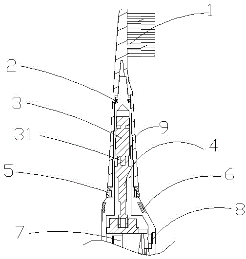
[0026] The reference signs therein are: toothbrush head body 1, muffler ring 2, micro motor 3, protruding column 31, support rod 4, color ring 5, elastic body rubber coating 6, bracket 7, handle 8, first damping rib 81, the second damping rib 82, the transmission rod 9.

[0027] Such as Figure 1 to Figure 9 As shown, the present invention

[0028] A sonic toothbrush vibration structure that effectively reduces the vibration of the handle, including a handle 8 and a micro motor 3 that can generate vibration output, wherein the handle 8 is molded as a whole with a transmission rod 9 that can transmit vibration to the toothbrush head body 1, the micro The motor 3 is fixed in the upper inner cavity of the transmission rod 9, and the...


PUM


Abstract

The invention provides a sonic toothbrush vibration structure for effectively reducing vibration of a handle. The sonic toothbrush vibration structure comprises the handle and a micro motor capable of generating vibration output, wherein a transmission rod which is formed by overall molding and transmits vibration to a toothbrush head body is arranged on the handle; the micro motor is fixed in an inner cavity of the upper part of the transmission rod; the transmission rod is in a flexible connection with the handle by a first damping rib long in axial direction and short in horizontal direction; a bracket is fixed in the handle; the lower part of the micro motor is connected with a support rod; the support rod is in the flexible connection with a second damping rib; the transmission rod and the support rod are driven by the micro motor to generate relative vibration with the handle; and high-frequency vibration generated by the transmission rod and the support rod is isolated with the handle by the first damping rib and the second damping rib. The sonic toothbrush vibration structure has the advantages of simple structure, reasonable design, convenience in carrying, stable and reliable working performance, relatively wide application scope, and the like and is an ideal tooth-cleaning and tooth-protecting appliance.

Description

technical field [0001] The invention relates to a toothbrush technology for cleaning teeth, in particular to a vibration structure of a sonic toothbrush which can effectively reduce the vibration of a handle. Background technique [0002] Toothbrush is the most commonly used tool for cleaning teeth. It is used to remove bacteria, tartar and small debris attached to the teeth. It can prevent periodontal diseases and protect people's oral hygiene and dental health. Toothbrushes on the market now Variety, structure is different, for example Chinese patent, patent number: ZL200620102401.9 discloses a kind of sonic vibration toothbrush, comprises the brush head that is provided with bristles, the brush neck bar and the vibrating part that doubles as the brush handle, and the vibrating part is provided with vibrating The joint is connected to the brush neck rod through the vibration joint, and other components such as the vibration source motor, the vibration rod and the main body...

Claims


Application Information

Patent Timeline
Patent Type & Authority Applications(China)
IPC IPC(8): A61C17/34
Inventor 罗宁刘会明蔡延钟彭伟兵
Owner NINGBO SEAGO ELECTRIC
Why Eureka
Try Eureka