Full-automatic edge painting machine

An oil edge machine, fully automatic technology, applied to the surface coating liquid device, small raw hide/large raw hide/leather/fur treatment, leather surface treatment, etc., can solve the problem of affecting the quality of oil edge, uneven oiling, Low work efficiency and other problems, to achieve the effect of high product quality, improved reliability, and reliable positioning

Active Publication Date: 2012-10-10
东莞宏川智能科技有限公司
View PDF5 Cites 8 Cited by
  • Summary
  • Abstract
  • Description
  • Claims
  • Application Information

AI Technical Summary

Problems solved by technology

[0002] In the prior art, the oil edge of leather and other workpieces is generally manually operated. This oil edge process has low work efficiency and uneven oiling; although there are also equipment that adopts automatic oil edge in the prior art, this automatic oil edge The oil edge machine generally adopts the method of passing materials or simulating manual operation. It can only oil edge regular-shaped leather, and if oil edge is performed on all the surrounding parts of the entire part, it must go through multiple processes, especially It is powerless for irregular shapes or curved corners. Moreover, most of the existing automatic oil edge machines are semi-automatic. Many tasks must be manually intervened to achieve cooperation between various processes, which is inefficient and There may also be misalignment of the workpiece during the oil edge process, which in turn affects the quality of the oil edge

Method used


Image

  • Full-automatic edge painting machine
  • Full-automatic edge painting machine
  • Full-automatic edge painting machine

Examples


Embodiment 1

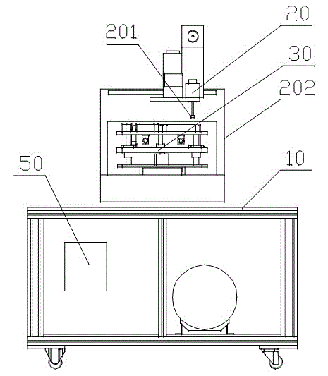
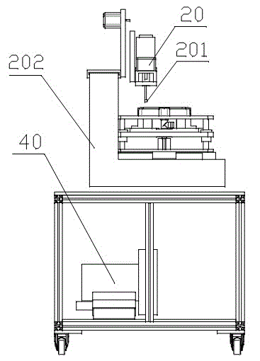
[0028] Such as figure 1 with figure 2 As shown, this example provides a fully automatic oil edge machine, including:

[0029] Rack 10;

[0030] The oil edge head assembly 20 installed on the frame 10, the oil edge head assembly 20 includes the oil nozzle head 201 and the mechanical shaft 202 for realizing the two-dimensional movement of the oil nozzle head 201;

[0031] A workpiece positioning device 30 for realizing oil edge positioning, the workpiece positioning device 30 is arranged on the frame 10, and is arranged below the oil edge head assembly 20;

[0032] A positioning pump 40 arranged in the frame 10, the positioning pump 40 is connected with the workpiece positioning device 30; and,

[0033] The control member 50 is used for controlling the oil edge process of the oil edge head assembly 20 , and controls the workpiece positioning device 30 and the positioning pump 40 to cooperate with the oil edge head assembly 20 respectively.

[0034] Wherein, the frame 10 bel...

Embodiment 2

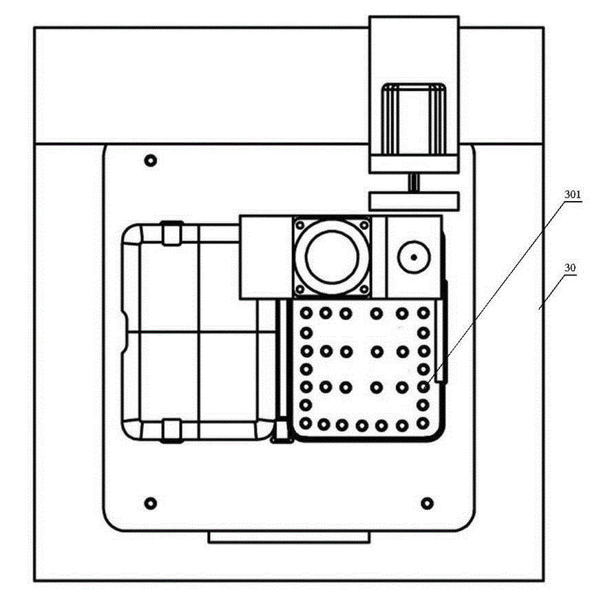
[0038] Such as image 3 As shown, on the basis of Embodiment 1, the further improvement of this example is that the upper surface of the workpiece positioning device 30 is provided with an air hole 301, the positioning pump 40 is an air pump, and the air hole 301 is connected to the air pump. Connection, in the oil edge process, the air hole 301 sucks the workpiece that needs oil edge through the air pump; after the oil edge is completed, the air pump stops working.

[0039] The upper surface of the workpiece positioning device 30 is used to place workpieces that require oil edge, and the upper surface of the workpiece positioning device 30 is provided with an air hole 301. During the oil edge process, the air pump can form a wind suction through the air hole 301, Suction the workpiece on the workpiece positioning device 30, and then on the basis of the positioning column, further realize the oil edge control without misalignment; after the oil edge is completed, the air pump ...

Embodiment 3

[0045] On the basis of Embodiment 1 or Embodiment 2, the oil nozzle head 201 in this example is connected to the control member 50 , and the control member 50 controls the fuel injection speed of the oil nozzle head 201 . Preferably, oil holes are evenly arranged on the circumference of the oil nozzle head 201 , and the oil nozzle head 201 realizes the self-rotation movement with adjustable speed during the oil edge process.

[0046] The control member 50 controls the oil injection speed of the oil nozzle head 201, which is convenient to control the oil injection speed of the oil nozzle head 201 according to different oil edge requirements or workpiece materials, improves the degree of customization, and has a high degree of humanized design. Furthermore, oil holes are uniformly arranged on the circumference of the oil nozzle head 201. During the oil edge process, the oil nozzle head 201 realizes the rotation movement, that is, the oil edge head assembly 20 controls the oil noz...


PUM


Abstract

The invention provides a full-automatic edge painting machine which comprises a framework, an edge painting head component, a workpiece positioning device, a positioning pump and a control component. The edge painting head component is mounted on the framework and consists of an oil nozzle head and a mechanical shaft, the oil nozzle head moves two-dimensionally by the aid of the mechanical shaft, the workpiece positioning device is used for positioning a painted edge, disposed on the framework and arranged below the edge painting head component, the positioning pump is arranged in the framework and connected with the workpiece positioning device, and the control component is used for controlling an edge painting process of the edge painting head component and controls the workpiece positioning device and the positioning pump to respectively match with the edge painting head component to paint the edge. The edge painting process is fully automatic, the workpiece positioning device and the positioning pump are controlled by the control component on the basis, dislocation in the edge painting process can be prevented, the full-automatic edge painting machine is high in positioning accuracy and can uniformly paint edges of irregular shapes and arc-shaped corners, and the quality of products with painted edges is high.

Description

technical field [0001] The invention relates to an oil edge machine, in particular to a fully automatic oil edge machine. Background technique [0002] In the prior art, the oil edge of leather and other workpieces is generally manually operated. This oil edge process has low work efficiency and uneven oiling; although there are also equipment that adopts automatic oil edge in the prior art, this automatic oil edge The oil edge machine generally adopts the method of passing materials or simulating manual operation. It can only oil edge regular-shaped leather, and if oil edge is performed on all the surrounding parts of the entire part, it must go through multiple processes, especially It is powerless for irregular shapes or curved corners. Moreover, most of the existing automatic oil edge machines are semi-automatic. Many tasks must be manually intervened to achieve cooperation between various processes, which is inefficient and It is also possible that the workpiece may be...

Claims


Application Information

Patent Timeline
Patent Type & Authority Applications(China)
IPC IPC(8): B05C5/00B05C13/02C14C15/00C14C11/00
Inventor 柳朝晖余前晋谢志强李伟杨红
Owner 东莞宏川智能科技有限公司
Why Eureka
Try Eureka