
Electric spindle structure of work bench

A technology of electric spindle and workbench, which is applied in the direction of manufacturing tools, metal processing equipment, metal processing machinery parts, etc., can solve the problems of increasing equipment investment cost and poor versatility of workbench electric spindle, so as to reduce input cost and have good versatility Effect

Active Publication Date: 2012-10-10
WUXI MACHINETOOL
View PDF5 Cites 2 Cited by
  • Summary
  • Abstract
  • Description
  • Claims
  • Application Information

AI Technical Summary

Problems solved by technology

[0002] The existing electric spindle of the workbench cooperates with the suction cup to hold the workpiece. Since the air passages evenly distributed on the suction cup are connected to each other, the electric spindle of the workbench only needs one air pipe to complete the communication with the air passage of the suction cup. To hold workpieces of fixed size, since the worktable electric spindle can only correspond to the suction cup for holding fixed-size workpieces, each workpiece of each size needs to correspond to different worktable electric spindles, which makes the versatility of the worktable electric spindle poor and increases the equipment cost. Input costs

Method used


Image

  • Electric spindle structure of work bench

Examples


Embodiment Construction

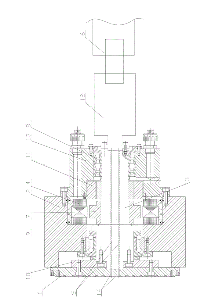
[0009] See figure 1 , which includes a front cover 1, a housing 2, a main shaft rear cover 13, a rotating shaft 3, a motor 4, and a resolver 5. The central area of ​​the rotating shaft 3 is provided with an air passage 5, and the air passage 5 is connected to a vacuum valve 6 at its tail. The cavity formed by the body 2 and the main shaft back cover 13 is equipped with a rotating shaft 3, a motor 4, and a resolver 11. The output end of the rotating shaft 3 is fastened to the front cover 1, and the rotating shaft 3 is fastened to the rotor 7 of the motor 4. The resolver 11 is set on one end of the rotating shaft 3. There are at least two air passages 5 in the central area of ​​the rotating shaft 3. The tail of each air passage 5 is connected to the vacuum valve 6 through a rotary joint 12. The front cover 1 corresponds to each air passage 5. There are through holes 14 in the positions respectively.

[0010] The rear end of the rotating shaft 3 is supported in the inner cavity ...


PUM


Abstract

The invention provides an electric spindle structure of a work bench. After an electric spindle of the work bench is assembled with a suction cup, different sizes of work-pieces can be held, the generality of the electric spindle of the work bench is good, and the invested cost of equipment is reduced. The electric spindle structure of the work bench comprises a front cover, a spindle rear cover, a shell, a rotating shaft, a motor and a rotary converter, wherein a gas circuit is arranged in a center area of the rotating shaft; the gas circuit is communicated with a vacuum valve at the tail part; the rotating shaft, the motor and the rotary converter are arranged inside a cavity formed by the shell and the spindle rear cover; the front cover is fixedly connected with output end of the rotating shaft; the rotating shaft is fixedly connected with a rotor of the motor, and the rotary converter is sleeved at one end of the rotating shaft. The electric spindle structure of the work bench is characterized in that at least two gas circuits are arranged in the centre area of the rotating shaft; the tail part of each gas circuit is respectively connected with the vacuum valve through a rotary joint, and through holes are respectively formed on the part of the front cover corresponding to each gas circuit.

Description

technical field [0001] The invention relates to the technical field of the spindle structure of a machine tool, in particular to the electric spindle structure of a workbench. Background technique [0002] The existing electric spindle of the workbench cooperates with the suction cup to hold the workpiece. Since the air passages evenly distributed on the suction cup are connected to each other, the electric spindle of the workbench only needs one air pipe to complete the communication with the air passage of the suction cup. To hold workpieces of fixed size, since the worktable electric spindle can only correspond to the suction cup for holding fixed-size workpieces, each workpiece of each size needs to correspond to different worktable electric spindles, which makes the versatility of the worktable electric spindle poor and increases the equipment cost. Input costs. Contents of the invention [0003] In view of the above problems, the present invention provides a wor...

Claims


Application Information

Patent Timeline
Patent Type & Authority Applications(China)
IPC IPC(8): B23B19/02B23Q1/26B23Q3/02
Inventor 朱凯旋
Owner WUXI MACHINETOOL
Learn More