Ecological building and working method thereof

An ecological building and working method technology, applied in the directions of buildings, building components, building structures, etc., can solve the problems of unable to realize ideal ecological buildings, difficult to accurately grasp the amount of irrigation, low survival rate of trees, etc. The effect of rotten roots or dry and high tree survival rate

Active Publication Date: 2012-10-10
莫剑峰
View PDF8 Cites 12 Cited by
  • Summary
  • Abstract
  • Description
  • Claims
  • Application Information

AI Technical Summary

Problems solved by technology

[0003] In existing buildings, flowerpots, large vats or directly on the floor structure are often used for roof greening and planting, but they are mainly shrubs, which have small planting area, difficult maintenance, and difficult to accurately control the amount of water. problems such as low survival rate of trees, high maintenance cost, failure to realize ideal ecological buildings, and difficulty in effective large-scale planting and promotion in batches

Method used


Image

  • Ecological building and working method thereof

Examples


Embodiment 1

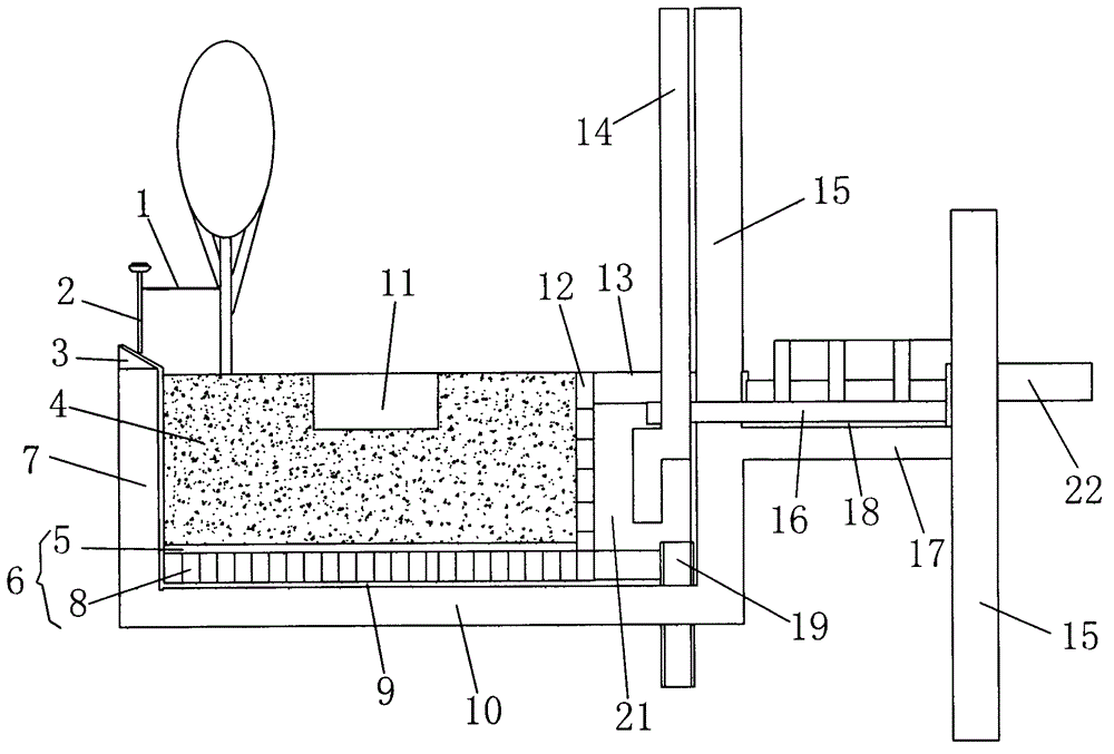
[0027] See figure 1 , The ecological building of the present embodiment is a multi-storey building or a high-rise building, etc., which includes a cavity located on one side of the wall.

[0028] The cavity includes: a planting cavity 4 and an energy storage cavity 6 separated by water-permeable materials.

[0029] The water-permeable material 8, such as water-permeable porous bricks or any water-permeable material that can freely circulate water sources, has sufficient strength to support the pressure of the planting cavity above, and realizes water-soil separation through the water-permeable material.

[0030] The energy storage chamber 6 is laid with the water seepage material 8 for seeping water into the soil in the planting chamber; The ends are connected; the energy storage chamber 6 is provided with a positioning drain pipe 19 for downward drainage, and the height of the entrance of the positioning drain pipe discharge pipe 19 is suitable for making the water level in ...

Embodiment 2

[0048] The building can also be a single-story building, and the water of the rainwater and / or residual water collection device and / or the water in the domestic waste water drain pipe 16 is discharged into the energy storage chamber 6; the positioning drain pipe 19 will be higher than the inlet water directly into the underground water storage tank.

Embodiment 3

[0050] The building can also be an elevated road or an overpass. When in use, the rainwater on the elevated road or overpass is discharged into the energy storage chamber through a drainpipe; into the next accumulator chamber.


PUM


Abstract

The invention relates to an ecological building which is convenient to construct, low in maintenance cost, high in survival rate of trees and easy to popularize and apply within a large range, and a working method of the ecological building. The ecological architecture comprises an ecological building cavity arranged at the top of a building, or the side of the building or the ground, wherein the cavity comprises a planting cavity and an energy storing cavity partitioned by a permeable material up and down; the permeable material for permeating soil in the planting cavity is paved inside the energy storing cavity; the energy storing cavity is connected with the tail ends of a rainwater and / or remained water collecting device and / or a sanitary wastewater discharge pipe; a locating discharge pipe for draining downwards is arranged inside the energy storing cavity; and a located inlet is lower than the water level, namely the height of the permeable material, in the energy storing cavity to prevent the planting cavity from being directly soaked into water, so as to prevent soil to be too wet so as to prevent the root of a plant from being rotted. On the other hand, the locating discharge pipe is suitable for keeping a certain water level in the energy storing cavity and can prevent the plant from being dried up due to the water loss of the energy storing cavity.

Description

technical field [0001] The invention relates to the technical field of ecological buildings, in particular to an ecological building with easy maintenance, low cost and high tree survival rate for planting trees in buildings (such as high-rise residential buildings, commercial office buildings, viaducts or overpasses, etc.) and arid areas. Architecture and its working methods. Background technique [0002] In modern cities where the urban green area is gradually shrinking, how to plant trees on buildings (such as high-rise residential buildings or commercial office buildings, etc.) to save land resources, expand green areas, purify air quality, beautify urban landscapes, reduce carbon emissions, and reduce thermal effects It is the trend of urban development to reduce urban noise and create a livable environment. [0003] In existing buildings, flowerpots, large vats or directly on the floor structure are often used for roof greening and planting, but they are mainly shrubs...

Claims


Application Information

Patent Timeline
Patent Type & Authority Applications(China)
IPC IPC(8): E04B1/00A01G9/02E04C1/39A01G27/02E03F5/04E01D19/00E01D19/08
CPCA01G9/02E04B1/00A01G27/06A01G9/28E04B1/34
Inventor 莫剑峰
Owner 莫剑峰
Why Eureka
Try Eureka