Bicycle auxiliary apparatus

An auxiliary device and bicycle technology, which is applied to bicycle accessories, vehicle parts, transportation and packaging, etc., can solve the problems of low use cost, energy waste, inconvenient auxiliary power charging, etc., achieve low production cost and use cost, and improve conversion. Efficiency and simple structure

Active Publication Date: 2014-07-09
蚌埠中知知识产权运营有限公司
View PDF4 Cites 0 Cited by
  • Summary
  • Abstract
  • Description
  • Claims
  • Application Information

AI Technical Summary

Problems solved by technology

[0003] In order to solve the problems of energy waste of existing bicycles and inconvenient charging of auxiliary power supplies, the invention discloses a bicycle auxiliary device to achieve the goals of energy saving, convenient use, and low use cost

Method used


Image

  • Bicycle auxiliary apparatus
  • Bicycle auxiliary apparatus
  • Bicycle auxiliary apparatus

Examples


Embodiment 1

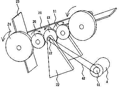
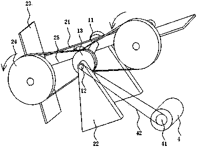
[0022] like figure 1 As shown, a bicycle auxiliary device includes a wind energy transmission device, and the wind energy transmission device includes a support base 22 fixedly connected to the bicycle, a central shaft 11 rotatably connected to the support base 22, and a fixed connection to the support base 22. The central gear 13 on the seat 22, the rotating bracket 21 fixedly connected to the central shaft 11, the first flywheel 12 coaxially and fixedly connected to the rotating bracket 21, and the rotatable and symmetrical on the rotating bracket 21 The fan blades 23 are distributed on both sides of the central axis 11; the fan blades 23 are two; and the planes of the two fan blades 23 are perpendicular to each other.

[0023] An angle adjustment gear 24 is fixedly connected to the fan blade 23 coaxially. A driven gear 25 is also arranged between the angle adjustment gear 24 and the central gear 13. The angle adjustment gear 24, the driven gear 25 and the The central gears...

Embodiment 2

[0027] The rest is the same as the first embodiment, the difference is that the angle adjustment gear 24 is directly meshed with the central gear 13, and the driven gear 25 is not provided in the middle.

Embodiment 3

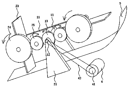
[0029] like figure 2 As shown, the rest is the same as that of Embodiment 1, except that the support base 22 is further provided with a wind deflector 5 . The wind deflector 5 is placed below the two wind blades 23 , and the side of the wind deflector 5 facing the forward direction is horizontal or has a downward bending amplitude, so as to introduce wind force, which rotates backward along the wind blade 23 The envelope curve is curved, so as to introduce more wind force to the rear fan blades 23 and reduce the influence of the front fan blades 23 on the rear fan blades 23 . At the same time, the wind deflector 5 causes a negative pressure between the wind vane 23 and the wind deflector 5 due to the fast airflow, so that the wind vane 23 generates a greater torque.


PUM


Abstract

This invention discloses a bicycle auxiliary apparatus, which can, through using wind blades, drive a rotation support to revolve, converting the wind energy of the flowing air to the mechanical energy when a bicycle moves forward. Through meshing between gears, the mechanical energy is transmitted to provide kinetic energy to the bicycle, or converted to the electric energy by driving a generator. The electricity energy is either supplied to electric equipment or stored in a storage battery to be prepared for the electric equipment when needed. At meantime, the wind blades can perform self-rotation, with the angle of a wind blade at the same position being consistent with the angle of the previous one after the rotation support rotates 180 degrees, so that the the area of the weather side of each wind blade is the greatest and the conversion efficiency of the wind energy is effectively improved. With a simple structure, the power energy storage device can be downsized, thereby enabling the production cost and usage cost to be lower.

Description

technical field [0001] The invention relates to a bicycle auxiliary device, in particular to a bicycle auxiliary device using wind power generation and energy storage. Background technique [0002] At present, whether the bicycle is driven by manpower or battery, there is energy loss during the driving process. For example, when going downhill, part of the potential energy is converted into mechanical energy to provide kinetic energy for the bicycle, and part of it is dissipated in other forms. Among the mechanical energy, there are also Part of it is converted into heat energy by deceleration and braking, resulting in a waste of energy. For human-powered bicycles, when the rider is tired, there is no auxiliary power, so they can only stop and rest. In addition, human-powered bicycles need to provide night lighting and electricity. When a speaker is used, an additional battery needs to be installed, but the battery can only be charged or replaced with a dry battery where the...

Claims


Application Information

Patent Timeline
Patent Type & Authority Patents(China)
IPC IPC(8): F03D9/00F03D1/06F03D1/04B62M6/00B62J6/06F03D9/11F03D9/25F03D9/32
CPCY02E10/721Y02E10/725Y02E10/72Y02E70/30Y02P70/50
Inventor 黄建辉
Owner 蚌埠中知知识产权运营有限公司
Why Eureka
Try Eureka