
A vortex cyclone type textile fabric dust removal and anti-wrinkle device
A textile fabric and cyclone technology, which is applied in the field of vortex cyclone type textile fabric dust removal and anti-wrinkle device, can solve the problems of difficult to achieve dust removal effect, affect the dust removal effect, function, etc., to improve the dust removal effect, increase the dust removal time, and make it easier to remove Effect
- Summary
- Abstract
- Description
- Claims
- Application Information
AI Technical Summary
Problems solved by technology
Method used
Image

Examples
Embodiment 1
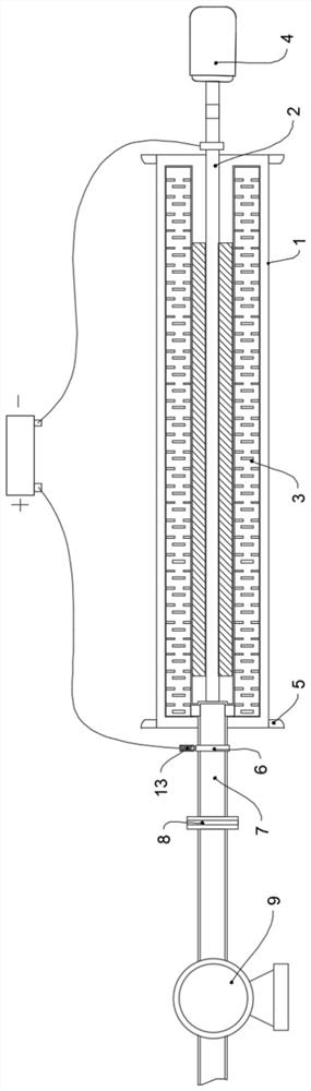
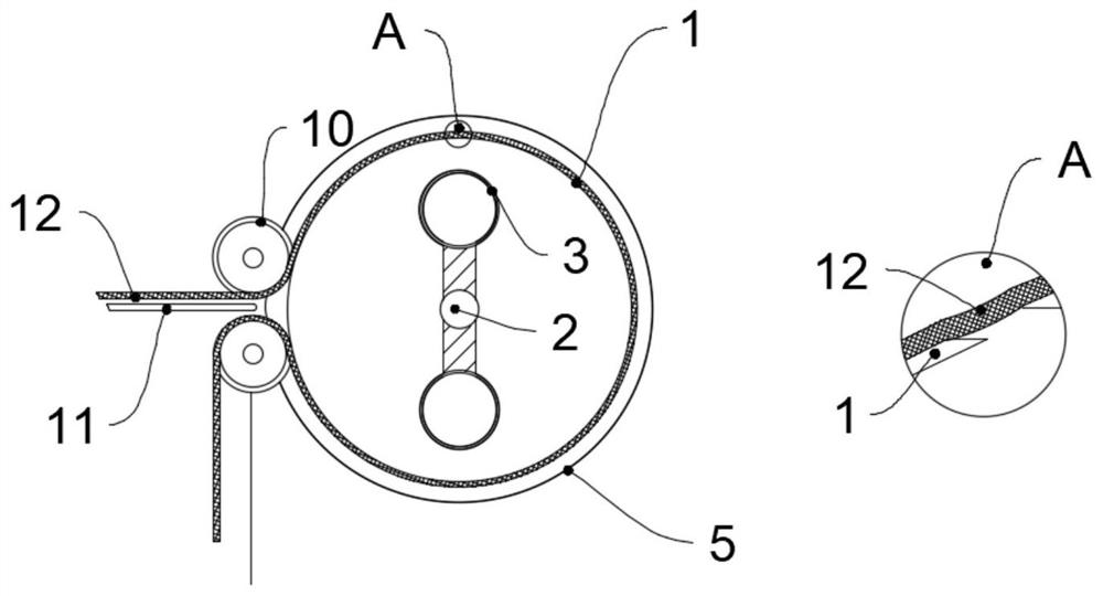
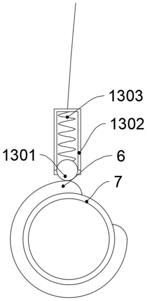
[0027] Such as Figure 1-3 As shown, a vortex cyclone type textile fabric dust removal and anti-wrinkle device includes an outer cylinder 1, the outer cylinder 1 is in contact with the surface of the textile fabric 12, the inside of the outer cylinder 1 is provided with a rotating shaft 2, and the rotating shaft 2 is flexibly connected with the outer cylinder 1 , the rotating shaft 2 is fixedly connected with two exhaust tubes 3 through a fixed frame, and the two exhaust tubes 3 are placed symmetrically at 180° with the axis of the rotating shaft 2 as the center. The right end passing through the outer cylinder 1 is fixedly connected to the motor 4 through an insulating joint. The insulating joint can prevent the current from being transmitted to the motor 4 through the rotating shaft 2 and affect the normal operation of the motor 4. The motor 4 can be used by Yulin Tongchuang Automation Technology Co., Ltd. The company's HG-KN43BJ-S100 Mitsubishi servo motor, the side of the ...
Embodiment 2
[0038] Such as Figure 4 As shown, the difference between this embodiment and Embodiment 1 is that: a second incomplete ring 14 fixedly connected to the outer wall of the exhaust duct 7 is provided between the rotary joint 8 and the first incomplete ring 6, and the second The incomplete ring 14 is provided with a gap, and the two sides above the second incomplete ring 14 are respectively provided with an elastic connecting device 13, the end of the left elastic connecting device 13 is fixedly connected with a wire, and the right elastic connecting device The end of 13 is connected with power supply negative pole by lead.
[0039] More specifically, a solenoid valve 15 is arranged between the rotary joint 8 and the exhaust fan 9, and the solenoid valve 15 is fixedly connected to the pipeline. The electrical device 13 is connected by wires.
[0040] working principle:
[0041] On the basis of Embodiment 1, as an optimization, by setting the second incomplete ring 14 and the e...
PUM
 Abstract
Description
Claims
Application Information