
Mask film plate and manufacturing method thereof

A mask and display substrate technology, applied in ion implantation plating, metal material coating process, coating and other directions, can solve the problems of prone to wrinkles, large differences, no evaporation of organic materials, etc., to improve the flatness degree, ensure quality, and improve the effect of product quality

Active Publication Date: 2016-07-27
BOE TECH GRP CO LTD +1
View PDF3 Cites 34 Cited by
  • Summary
  • Abstract
  • Description
  • Claims
  • Application Information

AI Technical Summary

Problems solved by technology

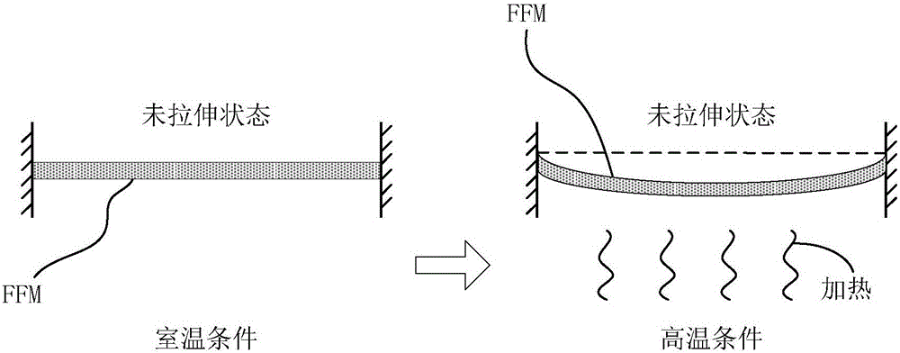
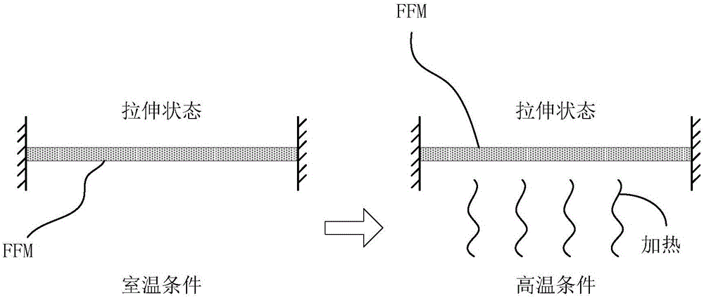
[0005] However, because the thickness of the FMM is very thin, it is prone to wrinkles during the stretching process, and the wrinkles will be intensified when it is attracted by the magnetic field in the evaporation chamber, resulting in poor surface flatness of the FMM, especially for the surface closest to the frame. Panel, its adhesion to the glass substrate varies greatly at different positions, which eventually leads to the fact that the organic material is not evaporated to the position that should be evaporated, resulting in color mixing when the Panel is lit
[0006] It can be seen that the quality of FMM used in the evaporation process is difficult to control, and this shortcoming has become one of the main bottlenecks restricting the development of AMOLED technology.

Method used


Image

  • Mask film plate and manufacturing method thereof
  • Mask film plate and manufacturing method thereof
  • Mask film plate and manufacturing method thereof

Examples


Embodiment Construction

[0030] The technical solutions in the embodiments of the present invention will be clearly and completely described below in conjunction with the accompanying drawings in the embodiments of the present invention. Obviously, the described embodiments are only a part of the embodiments of the present invention, rather than all the embodiments. Based on the embodiments of the present invention, all other embodiments obtained by those of ordinary skill in the art without creative efforts shall fall within the protection scope of the present invention.

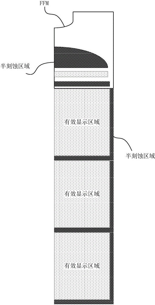
[0031] In order to avoid the appearance of wrinkles, the current approach is: for FMM, half-etched (HalfEtch) areas are designed around the area corresponding to the active area (ActiveArea) of each Panel and at both ends of the assembly area. Easy to understand, please refer to Figure 2A ( Figure 2A It is a schematic diagram of the distribution of the half-etched area on a 1 / 4 vapor-deposited substrate according to the prior art). S...


PUM


Abstract

The invention discloses a mask film plate and a manufacturing method thereof. The mask film plate is used for evaporating a display substrate, and comprises a pattern part and a stress buffer part, wherein the pattern part corresponds to a display area of the display substrate; the stress buffer part corresponds to at least one part of a non-display area of the display substrate; multiple first grooves are formed in one side of the stress buffer part; multiple second grooves are formed in the other side of the stress buffer part; and first projections of the first grooves on the plane where the mask film plate is located do not intersect with second projections of the second grooves on the plane where the mask film plate is located. The quality of the mask film plate in the evaporating process is guaranteed, so that the effect of improving the AMOLED product quality is achieved.

Description

Technical field [0001] The invention relates to the field of display technology, in particular to a mask and a manufacturing method thereof. Background technique [0002] OLED (Organic Light-Emitting Diode, Organic Light Emitting Diode) is a carrier double injection light emitting device, which emits light from electrons injected by electrodes under the driving of an external voltage. By adjusting the external voltage, the brightness of each red, green, and blue LED can be changed, and various colors of light can be obtained. OLED has the following advantages: (1) simple structure, because it does not require a backlight, it can be made as thin as paper; (2) true color, because it is a light-emitting body, the light-emitting color can achieve pure color saturation, And in the temperature range between minus 45 degrees Celsius and above zero degrees Celsius, the color will not change. Unlike liquid crystal technology, the color will change with the change of temperature or viewin...

Claims


Application Information

Patent Timeline
IPC IPC(8): C23C14/04C23C14/24
CPCC23C14/042C23C14/24
Inventor 嵇凤丽梁逸南白珊珊
Owner BOE TECH GRP CO LTD
Learn More