Cracking-gas fuel injection device for chemical regenerative cycle

A technology of fuel injection device and chemical regenerative cycle, applied in combustion chambers, combustion methods, combustion equipment, etc., can solve the problem of no swirl vanes, and achieve the effect of preventing flow field fluctuations, compact structure, and overcoming combustion instability

Inactive Publication Date: 2014-08-20
三亚哈尔滨工程大学南海创新发展基地
View PDF14 Cites 0 Cited by
  • Summary
  • Abstract
  • Description
  • Claims
  • Application Information

AI Technical Summary

Problems solved by technology

However, there is no swirl vane structure in this structure, and the shear flow field that can be generated by the swirl vane is not applied to the fuel mixing at the head of the combustion chamber.

Method used


Image

  • Cracking-gas fuel injection device for chemical regenerative cycle
  • Cracking-gas fuel injection device for chemical regenerative cycle
  • Cracking-gas fuel injection device for chemical regenerative cycle

Examples


Embodiment Construction

[0025] The present invention is described in more detail below in conjunction with accompanying drawing example:

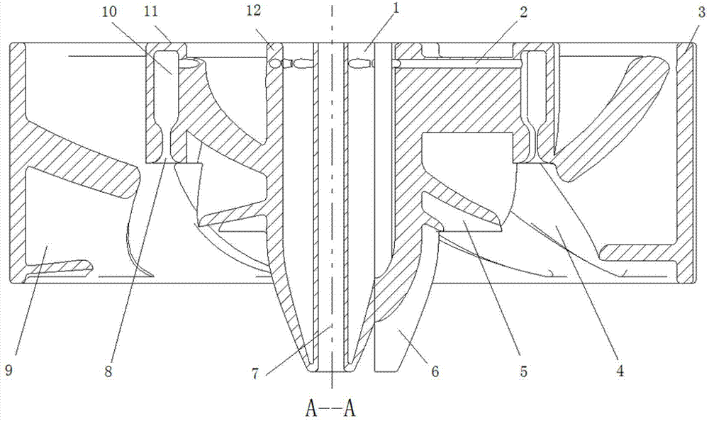
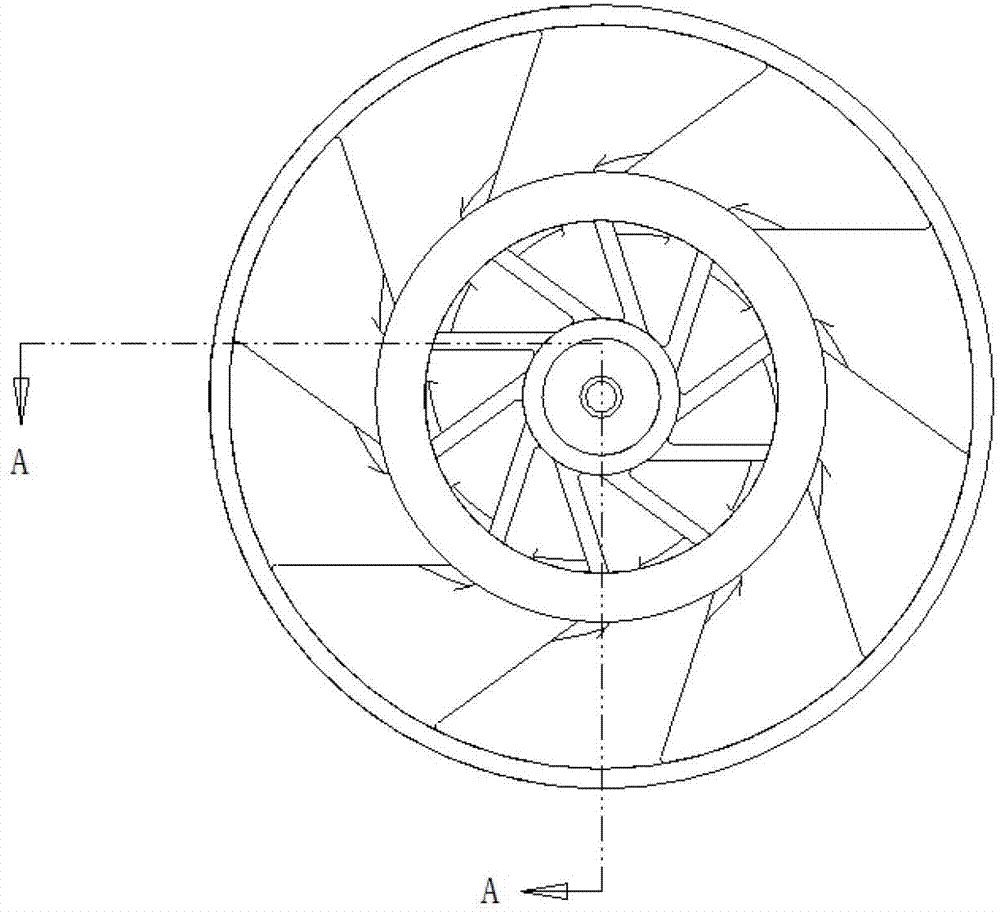
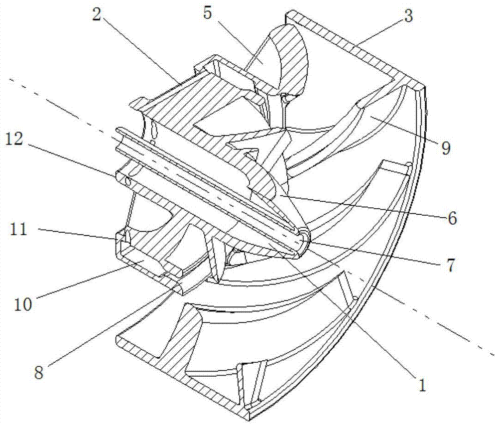
[0026] combine Figure 1~6 , the swirler includes a fuel supply channel 1, a gas channel 2 in the blade, an outer hub of the swirler 3, a diverging channel 4, an inner swirl blade 5, a central body cap 6, a central through hole 7, Coanda Nozzle 8, swirler blade 9, pyrolysis gas ring chamber 10, swirler middle hub 11, swirler inner hub 12. In addition, it also includes a schematic curve 13 of cracked gas fuel flow and a general schematic curve 14 of the expanding channel.

[0027] figure 1 and figure 2 Together, the working principle of the cracked gas fuel ring injection port is explained. The cracked gas first enters the nozzle through the fuel supply channel 1, and then enters the cracked gas ring cavity 10 through the vane gas channel 2 after encountering the blockage of the central body cap 6. During the process, a certain steady flow is carried out, and ...


PUM


Abstract

The invention aims at providing a cracking-gas fuel injection device for chemical regenerative cycle, comprising an inner hub, a middle hub, an outer hub, inner-stage swirl vanes, outer-stage swirl vanes and a center body cap hood, wherein the inner-stage swirl vanes are arranged between the inner hub and the middle hub; the outer-stage swirl vanes are arranged between the middle hub and the outer hub; a central through hole is arranged in the inner hub; a fuel feeding channel is formed between the inner hub and the central through hole and is closed by the center body cap hood; the inner hub is provided with an inlet channel of cracking gas fuel; the middle hub is provided with a cracking gas ring cavity; a spraying nozzle is arranged at the end part of the cracking gas ring cavity; a divergent channel is formed by the inner-stage swirl vanes and the outer-stage swirl vanes; and gas sprayed from the spraying nozzle enters a combustion chamber through the divergent channel. The cracking-gas fuel injection device provided by the invention has the advantages that the cracking gas fuel and air can be well mixed, so that the length of flame is further shortened, the length of the combustion chamber can be shortened, and further the structure of a gas turbine becomes compact.

Description

technical field [0001] The invention relates to a gas turbine, in particular to a fuel injection device for the gas turbine. Background technique [0002] With the advancement of technology, people's requirements for the performance of gas turbines are also getting higher and higher. In order to improve the performance of gas turbines, many advanced cycle methods have been continuously proposed, and the chemical regenerative cycle is an advanced cycle method. The working mode of the chemical regenerative cycle gas turbine CRGT determines that its combustor must adopt a dual-fuel system. The injection of liquid fuel generally uses centrifugal atomizing nozzles, and the mixing of gaseous fuel is one of the difficulties. [0003] As countries around the world pay more attention to environmental protection, it is the designer's most sought-after goal to make gas turbines operate efficiently and reduce a series of pollution generated during the work process. For combustors burn...

Claims


Application Information

Patent Timeline
Patent Type & Authority Patents(China)
IPC IPC(8): F23R3/38
Inventor 康振亚郑洪涛李智明杨仁杨洪磊刘倩张智博潘福敏
Owner 三亚哈尔滨工程大学南海创新发展基地
Why Eureka
Try Eureka