Full-serial plate shell heat exchanger

A heat exchanger, plate and shell technology, applied in the field of plate and shell heat exchangers, can solve the problems of unfavorable saving of land resources, unfavorable energy saving and emission reduction, increase of equipment cost, etc., and achieve raw material saving, light weight and low production cost Effect

Active Publication Date: 2012-10-10
GANSU LANPEC TECH +3
View PDF4 Cites 9 Cited by
  • Summary
  • Abstract
  • Description
  • Claims
  • Application Information

AI Technical Summary

Problems solved by technology

[0003] The purpose of the present invention is to provide a full-series plate-shell heat exchanger to solve the problem of simple series connection of multiple traditional plate-shell heat exchangers. The existing pressure drop loss is relatively prominent, which not only increases the cost of the equipment At the same time, it is not conducive to saving land resources, and it is not conducive to technical issues such as energy saving and emission reduction.

Method used


Image

  • Full-serial plate shell heat exchanger
  • Full-serial plate shell heat exchanger
  • Full-serial plate shell heat exchanger

Examples


Embodiment 1

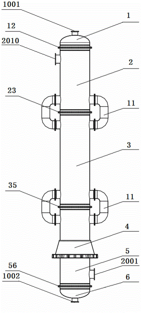
[0045] refer to Figure 1 to Figure 9 , a full series plate and shell heat exchanger, the cold and hot medium are arranged in counter flow. The hot medium goes straight in and out, and the cold medium goes in and out from the side. The invention relates to a full series plate and shell heat exchanger, including a head, a cylinder, a skirt, a plate bundle, a fluid distributor, a heat medium inlet, a heat medium outlet, a cold medium inlet, a cold and heat medium outlet, etc. part.

[0046] The full series plate and shell heat exchanger consists of an upper head 1, a lower head 6, a stage III cylinder body 2, a stage II cylinder body 3, a stage I cylinder body 5, a skirt seat 4, a plate bundle 9, a fluid distribution device 10 and so on.

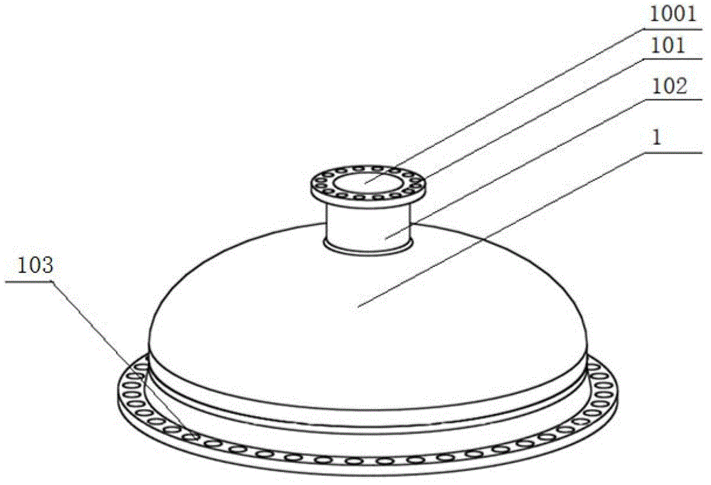
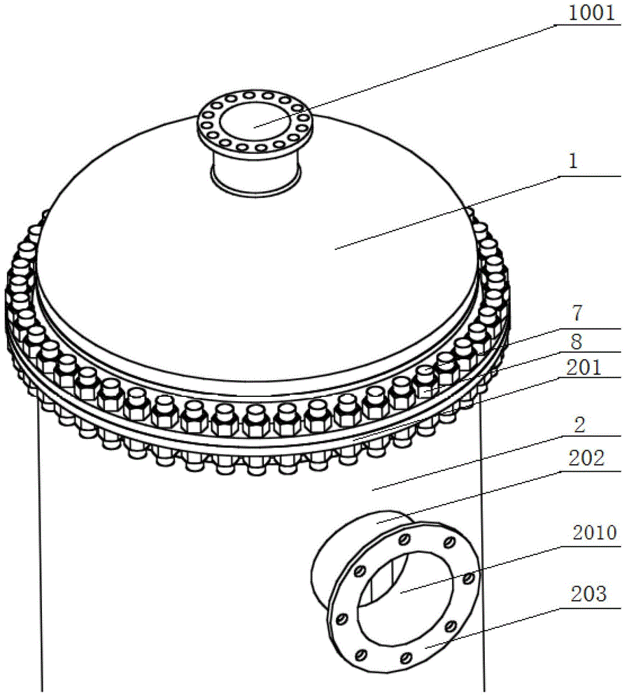
[0047] Upper head 1 is composed of forming head 1, connecting flange 101, head connecting pipe 102, equipment flange 103, etc. The rotating surface of forming head 1 can be divided into elliptical, spherical, butterfly, conical and other sh...

example 2

[0057] The manufacturing process of Example 2 is basically the same as that of Example 1. The difference is that there is only one group of cold medium outlets and inlets on the cylinder of Example 2 of this example, such as Figure 10 As shown, the cold medium can only flow in one direction.

[0058] Table 1 Comparison of the simple series connection between the full series plate and shell heat exchanger of the present invention and multiple traditional plate and shell heat exchangers

[0059]


PUM


Abstract

The invention discloses a full-serial plate shell heat exchanger which reduces the thermal stress of the structure to the minimum extent by adopting an assorting cylinder treatment mode. The structure of the full-serial plate shell heat exchanger mainly comprises an upper end enclosure, a lower end enclosure, an III-stage cylinder, a II-stage cylinder, a I-stage cylinder, a skirt, a lathed bundle, a fluid distributor and the like, wherein heat exchange of cold and hot media is finished in the lathed bundle, a shell formed by the cylinders, the end enclosures and an adapter tube is a main bearing element, the lathed bundle is arranged in the cylinders, and all cylinders are fixedly connected in series by an equipment flange through bolts. A channel consisting of the fluid distributor and used for stabilizing a first fluid pressure head is arranged between the cylinders; and a second fluid channel is communicated by a bypass adapter tube of all the cylinders. The fluid distributor comprises an upper baffle, a lower baffle, a drainage tube, an expansion ring and the like. The full-serial plate shell heat exchanger can solve the technical problems that a plurality of traditional simple serial plate shell type heat exchangers are serious in pressure drop loss, increase the equipment cost, waste land resources, are not beneficial to energy conservation and emission reduction, and the like.

Description

technical field [0001] The invention belongs to the technical field of plate-shell heat exchangers. Background technique [0002] The plate and shell heat exchanger is currently the most advanced heat exchanger in the world, with the advantages of high pressure resistance and high heat exchange efficiency. With the development of large-scale equipment, the thermal expansion of the heat exchanger plate bundle at high temperature also increases, resulting in bending of the weak parts of the plate, cracking of the weld seam, and even tearing of the plate. The reason is that the plate bundles are arranged longitudinally along the cylinder body. In the longitudinal direction, due to the long size of the plate bundles, the amount of expansion and deformation produced at high temperature is very large. Due to the limitation of the structure, the two ends of the plate bundle can only be welded and fixed in the cylinder during the manufacturing process, so that the two ends of the p...

Claims


Application Information

Patent Timeline
Patent Type & Authority Applications(China)
IPC IPC(8): F28D9/00F28F9/00F28F9/22
Inventor 胡国栋王纪兵
Owner GANSU LANPEC TECH
Why Eureka
Try Eureka