High temperature resistant spring-type device for measuring metallic material deformation

A technology of metal materials and measuring devices, which is applied to measuring devices, using stable tension/pressure to test the strength of materials, instruments, etc., can solve the problems of inability to measure the deformation of samples, insufficient measurement accuracy, and limited range, etc., to achieve Avoid eccentric stretching, easy installation and low cost

Inactive Publication Date: 2012-10-10
TONGJI UNIV
View PDF4 Cites 25 Cited by
  • Summary
  • Abstract
  • Description
  • Claims
  • Application Information

AI Technical Summary

Problems solved by technology

This kind of extensometer can only realize unilateral measurement of the deformation of the sample, so that the measurement of the deformation of the sample is greatly affected by the load eccentricity caused by the different axis of the testing machine, and the measurement accuracy is not high enough; its measuring range is limited, and the gauge length is less than 50mm ; Because most of them are imported products, the price is expensive
In addition, this kind of extensometer is mainly suitable for a single sample. For special multi-strand metal material samples without bosses such as steel strands and steel wire bundles, it can only measure the high-temperature deformation of the outer steel wires, but cannot measure The amount of deformation of the entire sample, so it is difficult to apply

Method used


Image

  • High temperature resistant spring-type device for measuring metallic material deformation
  • High temperature resistant spring-type device for measuring metallic material deformation

Examples


Embodiment 1

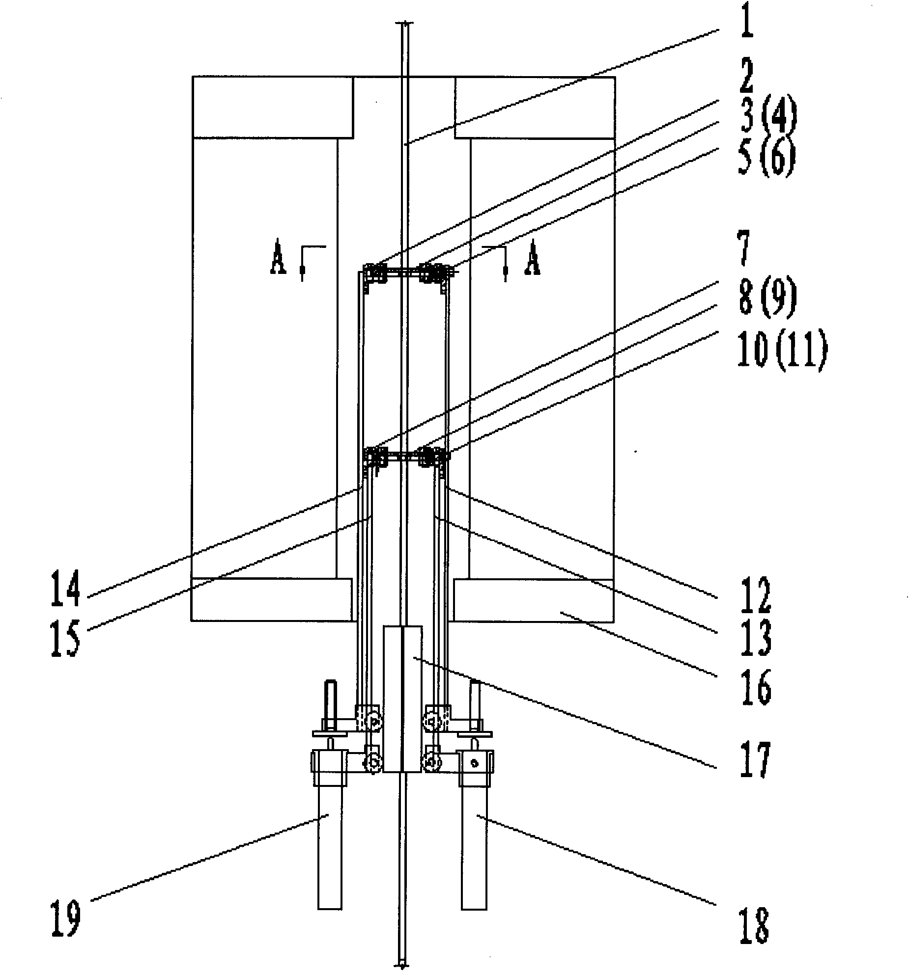
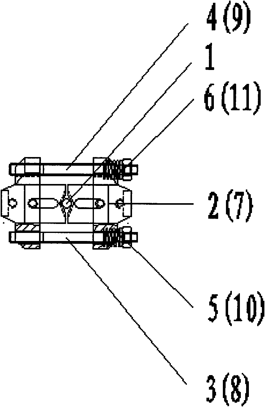
[0013] Such as Figure 1~2 As shown, a high-temperature-resistant spring-type metal material deformation measuring device includes a metal material sample 1, an upper clamping block 2, a piercing rod a3, a piercing rod b4, a high-temperature-resistant spring a5, a high-temperature-resistant spring b6, a lower clamping block 7, Through rod c8, through rod d9, high temperature resistant spring c10, high temperature resistant spring d11, extension rod a12, extension rod b13, extension rod c14, extension rod d15, high temperature furnace 16, guide block 17, differential transformer displacement sensor a18, Differential transformer displacement sensor b19.

[0014] First clamp the metal material sample 1 with the upper and lower chucks of the tensile testing machine, and then fix the two knife edges of the upper clamp block 2 to the upper gauge end of the sample according to the determined sample gauge distance, and the two knife edges pass through the two A parallel piercing rod ...


PUM


Abstract

The invention relates to a high temperature resistant spring-type device for measuring metallic material deformation, which comprises high temperature resistant springs, an upper clamp splice, a lower clamp splice, extension rods, deformation sensors, and a high temperature furnace. The upper clamp splice and the lower clamp splice are both arranged in the high temperature furnace, and end portions thereof are provided with the high temperature resistant springs and are fixedly provided with the extension rods. Due to compacting forces of the high temperature resistant springs, in the process of the sample being extended longer and thinner by high temperature, edges of the upper clamp splice and the lower clamp splice are driven to move inwardly with even, and the sample is always clamped firmly. The lower ends of the extension rods extend from a lower opening of the high temperature furnace, and are connected with the deformation sensors at two symmetrical sides of the sample, such that a two-side measuring system is formed for measuring a deformation value of the sample. Compared with the prior art, the device, simple in structure and convenient in installation, can both measure the deformation values within a gauge length of common and special non-boss metallic material samples in a high temperature extension test, wherein the common non-boss metallic materials are wire materials, bar materials, tube materials, etc., while the special non-boss metallic materials are multi-ply type such as steel wire cables, etc.

Description

technical field [0001] The invention relates to the field of high-temperature tensile mechanical performance testing of metal materials, and is a technology for measuring the deformation within the gauge length when conducting high-temperature tensile tests on metal material samples without bosses such as wires, rods, pipes, and steel wire bundles. device. Background technique [0002] At present, when conducting high-temperature tensile tests on metal material samples without bosses (such as wires, rods, pipes, etc.) at home and abroad, when using a more accurate method to measure the deformation within the gauge length, the devices used are mostly side-inserted extensions. count. This kind of extensometer can only realize unilateral measurement of sample deformation, so that the sample deformation measurement is greatly affected by the load eccentricity caused by the different axis of the testing machine, and the measurement accuracy is not high enough; its measuring rang...

Claims


Application Information

Patent Timeline
Patent Type & Authority Applications(China)
IPC IPC(8): G01N3/18G01B21/32
Inventor 王烨华沈祖炎李元齐
Owner TONGJI UNIV
Why Eureka
Try Eureka