
Input current detection method and device of bridgeless pfc circuit

A technology of input current and detection device, applied in measurement device, output power conversion device, measurement current/voltage and other directions, can solve problems such as difficulty in sampling AC input current, and achieve the effect of reducing sampling difficulty

Active Publication Date: 2016-05-18
VERTIV CORP
View PDF6 Cites 1 Cited by
  • Summary
  • Abstract
  • Description
  • Claims
  • Application Information

AI Technical Summary

Problems solved by technology

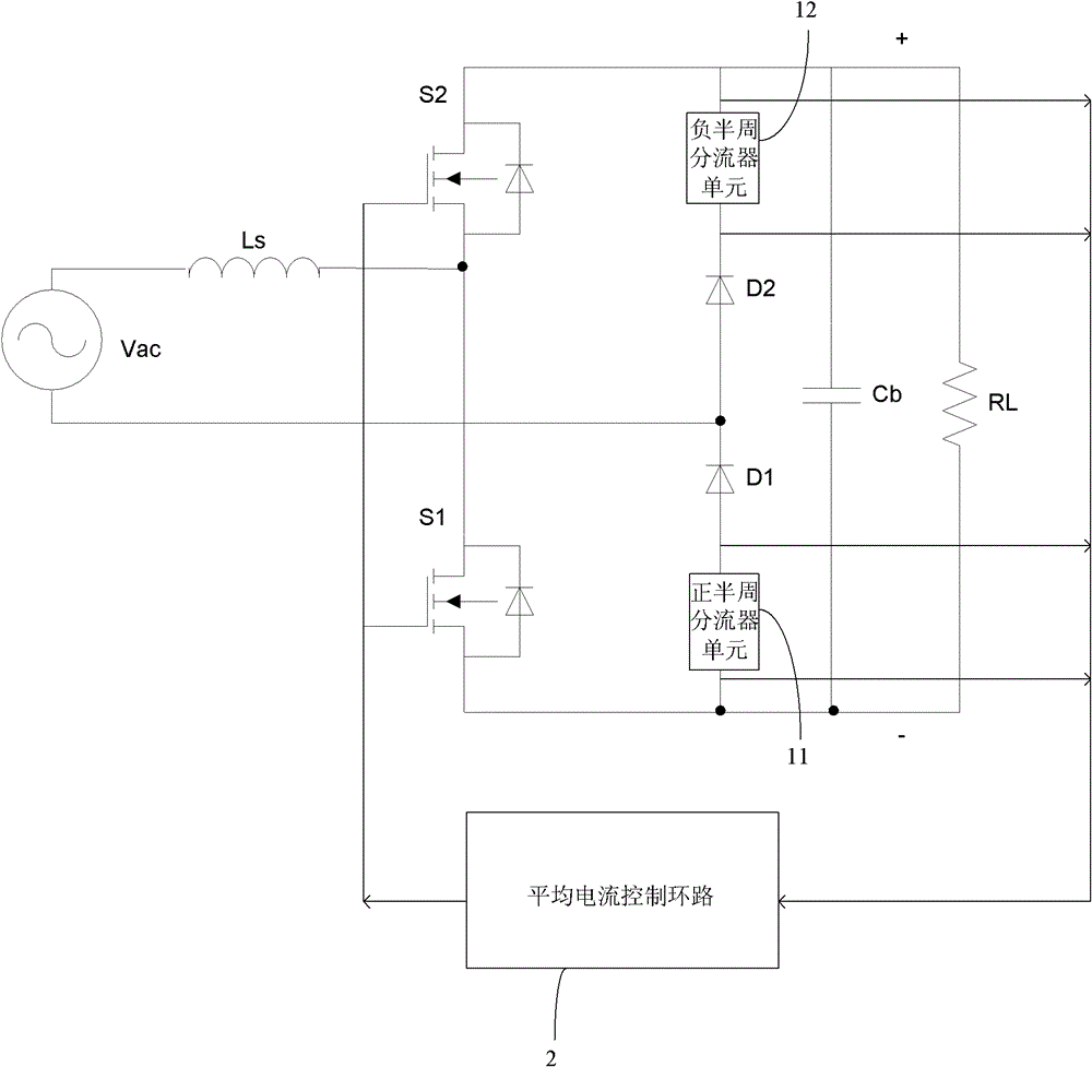
[0003] The purpose of the present invention is to provide an input current detection device for a bridgeless PFC circuit, which aims to solve the difficulty of directly sampling the AC input current in a bridgeless PFC circuit in the prior art; there is no relatively simple, convenient and effective Aiming at the problems of the current sampling scheme of the bridgeless PFC circuit working in the current continuous mode

Method used


Image

  • Input current detection method and device of bridgeless pfc circuit
  • Input current detection method and device of bridgeless pfc circuit
  • Input current detection method and device of bridgeless pfc circuit

Examples


Embodiment Construction

[0029] In order to make the object, technical solution and advantages of the present invention clearer, the present invention will be further described in detail below in conjunction with the accompanying drawings and embodiments. It should be understood that the specific embodiments described here are only used to explain the present invention, not to limit the present invention.

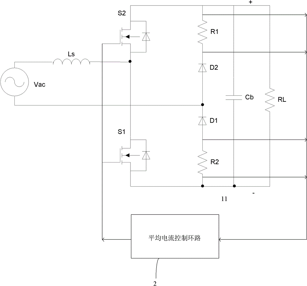
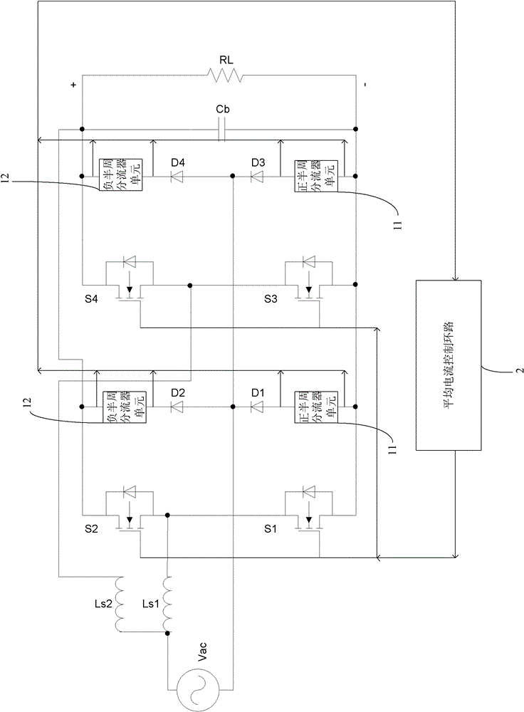
[0030] The input current detection device of the bridgeless PFC circuit of the present invention mainly includes two parts, namely: a current detection part and a calculation control part.

[0031] The bridgeless PFC circuit is connected between an AC power source and a load. In order to detect the input current in the bridgeless PFC circuit, that is, to detect the inductor current in the bridgeless PFC circuit, the present invention connects the positive half cycle shunt unit and The negative half-cycle shunt unit is used as the current detection part, so that in the positive half-cycle loop, the...


PUM


Abstract

The invention relates to a method and an apparatus for detecting an input current of a bridgeless PFC circuit. The method comprises the following steps of connecting a positive-half-cycle diverter unit in series in a positive-half-cycle loop of a bridgeless PFC branch and connecting a negative-half-cycle diverter unit in series in a negative-half-cycle loop of the bridgeless PFC branch, detecting voltages cross the two sides of the positive-half-cycle diverter unit and the negative-half-cycle diverter unit respectively, and thus calculating the input current through the bridgeless PFC circuit. Through connecting the positive-half-cycle diverter unit and the negative-half-cycle diverter unit in series in the positive-half-cycle loop and the negative-half-cycle loop of the PFC circuit respectively and by detecting the voltages of the two sides of the positive-half-cycle diverter unit and the negative-half-cycle diverter unit, an inductor current through the PFC circuit can be calculated simply, conveniently and effectively, timely sampling of the input current can be realized and a sampling difficulty of the input current through the bridgeless PFC circuit can be reduced.

Description

technical field [0001] The present invention relates to an input current detection method and device, more specifically, to a bridgeless PFC circuit input current detection method and device. Background technique [0002] Active power factor correction (APFC, ActivePowerFactorCorrection) is widely used in communication power supplies. In the control of APFC, it is necessary to sample the AC input current. In the bridgeless PFC circuit (especially, the totem pole bridgeless PFC circuit), the AC input is directly Current sampling is more difficult. At present, there is no relatively simple, convenient and effective current sampling scheme for a bridgeless PFC circuit operating in a continuous current mode (CCM, Current Continuous Mode). Contents of the invention [0003] The purpose of the present invention is to provide an input current detection device for a bridgeless PFC circuit, which aims to solve the difficulty of directly sampling the AC input current in a bridgeles...

Claims


Application Information

Patent Timeline
Patent Type & Authority Patents(China)
IPC IPC(8): G01R19/00H02M1/42
CPCY02B70/10Y02P80/10
Inventor 屈云生首福俊
Owner VERTIV CORP
Learn More