
Automatic modeling method of direct current transmission project network topology

A technology for DC engineering and network topology, applied in electrical digital data processing, instrumentation, computing, etc., can solve problems such as large workload, error-prone, and large modeling workload, and achieve good scalability and operability. , the effect of reducing technical requirements

Inactive Publication Date: 2014-01-22
南网电网科学研究院有限责任公司 +1
View PDF3 Cites 0 Cited by
  • Summary
  • Abstract
  • Description
  • Claims
  • Application Information

AI Technical Summary

Problems solved by technology

Since the two softwares only provide the most basic circuit components, to model DC engineering network topology, users first need to be particularly familiar with the system component library and DC transmission characteristics, and at the same time carry out reasonable equivalent modeling of DC engineering equipment , and secondly, it is necessary to convert the complicated engineering data into corresponding circuit component parameters, and the workload is very heavy
At the same time, the more complex the engineering wiring, the greater the workload of modeling and the more prone to errors

Method used


Image

  • Automatic modeling method of direct current transmission project network topology
  • Automatic modeling method of direct current transmission project network topology
  • Automatic modeling method of direct current transmission project network topology

Examples


Embodiment Construction

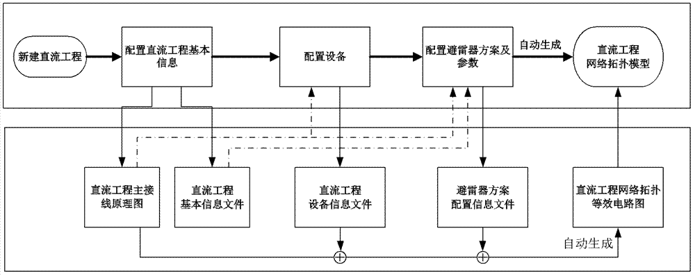
[0024] A DC engineering network topology automatic modeling method of the present invention comprises the following steps:

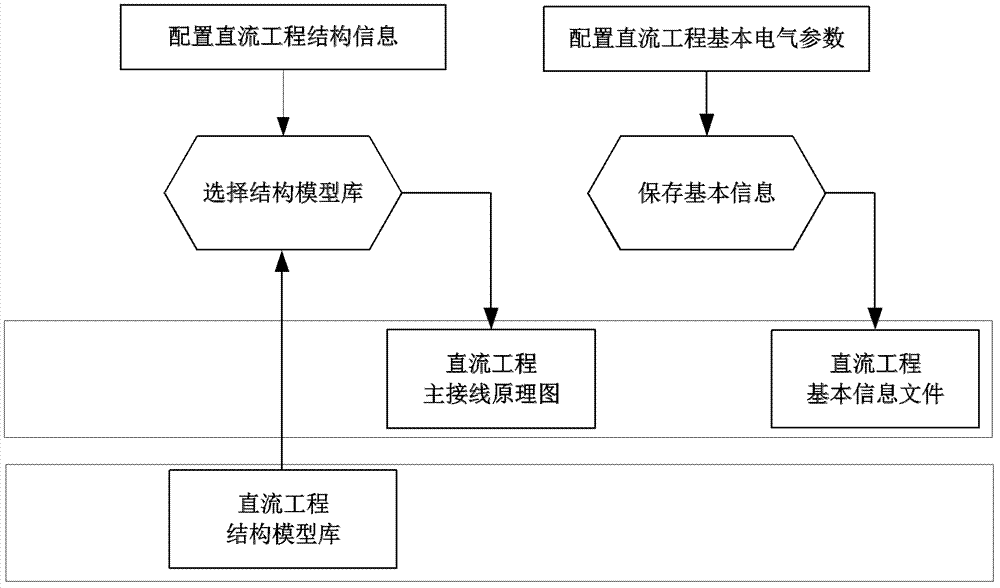
[0025] Step 1: Configure the basic information of the DC project, and automatically generate the main wiring diagram of the DC project, including:

[0026] 1.1) According to the user configuration, the structure information of the DC project is obtained, including the operation mode of the DC project, the transmission mode, the connection form of the converter, the type of the DC line and the pole line of the grounding pole line, and this information is used for the automatic modeling of the main wiring of the DC project.

[0027] 1.2) Obtain the basic electrical parameters of the DC project according to the user parameter configuration, and generate the basic information file of the DC project. The basic electrical parameters of the system include the rated power P r , rated voltage U r , rated current I r , Design trigger angle α, design cut-off ang...


PUM


Abstract

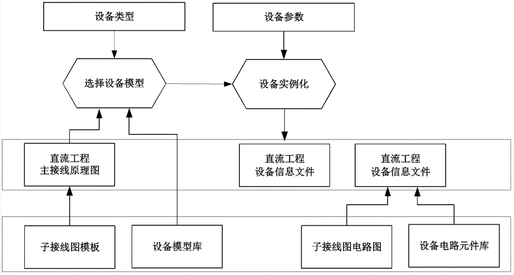
The invention discloses an automatic modeling method of direct current transmission project network topology. The method comprises loading a direct current project module according to direct current project structure information to generate a direct current project main connection schematic diagram, extracting a sub-connection diagram template, a device model, and circuit components according to the direct current project main connection schematic diagram, and then generating a direct current project device information file; configuring parameters and a position for a lightning arrester according to the direct current project main connection schematic diagram, and then generating a lightning arrester schema configuration information file; and completing the modeling of the direct current project network topology equipped with the lightning arrester and the generation of an equivalent circuit diagram by adopting the direct current project main connection schematic diagram as a template and combining the direct current project device information file and the lightning arrester schema configuration information file. The automatic modeling method of the invention presets a typical direct current project network topology module, various device types and equivalent models, and instantiation applications of the direct current project can be completed by just selecting a device type and a parameter configuration by users. Workload amount of the direct current project network topology equivalent and modeling is greatly reduced, and direct current project modeling efficiency is improved.

Description

technical field [0001] The invention belongs to the field of high-voltage direct current transmission system analysis, and in particular relates to an automatic modeling method for network topology of a direct current transmission project. Background technique [0002] my country's power grid is in a period of rapid development, and has now entered the stage of transition from a large regional power grid to a national interconnected power grid. With the implementation of the national networking project, DC transmission technology will play a leading role in the west-to-east power transmission and national networking. At the same time, the voltage level of DC projects is gradually increasing from 500kV to 800kV, and even has a tendency to develop to a higher voltage level. The DC operation mode is gradually developing from single-circuit to double-circuit. A series of technical and safety issues, such as more complex DC system failures, more serious losses and system problems...

Claims


Application Information

Patent Timeline
Patent Type & Authority Patents(China)
IPC IPC(8): G06F17/50
Inventor 何俊佳厉天威董曼玲黎小林吕金壮袁智勇项阳赵贤根张佳鑫
Owner 南网电网科学研究院有限责任公司
Learn More