
Wireless sensor implemented by using radio frequency identification (RFID) tag

A technology of RFID tags and wireless sensors, which is applied in the direction of recording carriers used in machines, instruments, and collaborative work devices, etc., can solve the problems of high cost and restrictions on wide application

Active Publication Date: 2012-10-10
广州市穗佳物流有限公司
View PDF4 Cites 5 Cited by
  • Summary
  • Abstract
  • Description
  • Claims
  • Application Information

AI Technical Summary

Problems solved by technology

[0010] The main problem of various current solutions is cost. Sensor networks based on 802.15.4 are all active sensors. Their reliability, maintenance requirements, and complexity all lead to high cost, which is the biggest problem restricting their wide application.

Method used


Image

  • Wireless sensor implemented by using radio frequency identification (RFID) tag
  • Wireless sensor implemented by using radio frequency identification (RFID) tag
  • Wireless sensor implemented by using radio frequency identification (RFID) tag

Examples


Embodiment Construction

[0023] The present invention will be further described below in conjunction with drawings and embodiments.

[0024] The present invention adopts far field (far field) very high frequency or RFID technology in microwave frequency band, and the passive tag adopts back scattering to modulate information. Based on the standard RFID tag circuit, make some changes to realize the interface with the 1-wire sensor.

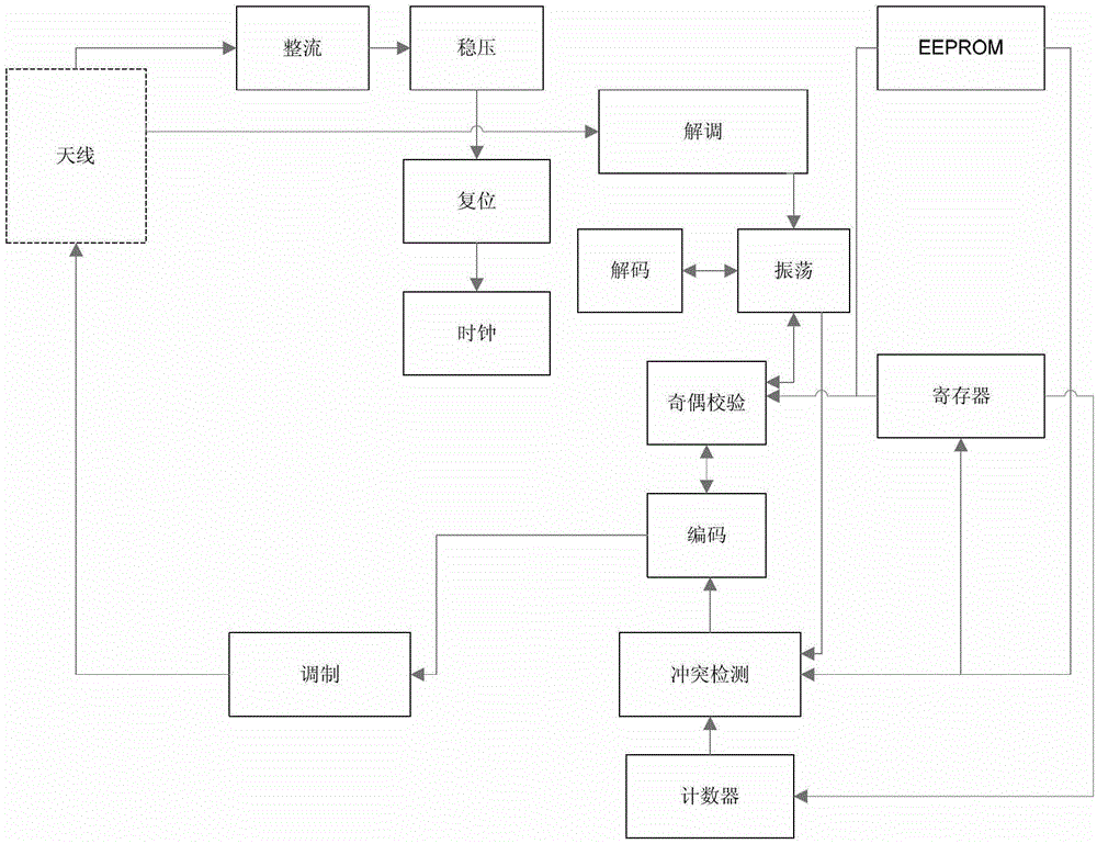
[0025] The RFID tag consists of an antenna, a radio frequency front-end circuit, a signal processing circuit, a conflict detection logic circuit, and an EEPROM. figure 1 It is a block diagram of a typical RFID tag structure.

[0026] The passive tag has no power supply, and its front-end circuit obtains power from the RF signal of the RFID reader, which is composed of rectification, voltage stabilization, reset (generate POR, power-on reset signal) and other circuits. Typically, RFID tag digital circuits consist of thousands of gate circuits, and more advanced RFID tags ...


PUM


Abstract

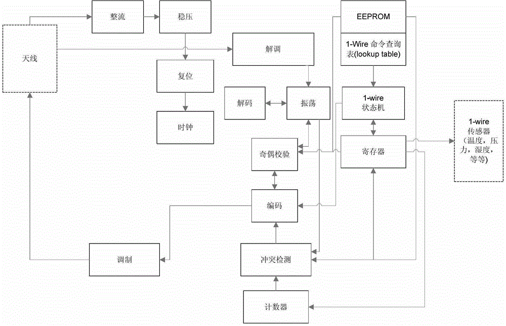
The invention discloses a wireless sensor implemented by using a radio frequency identification (RFID) tag. The wireless sensor comprises the RFID tag and a 1-wire state machine, wherein the RFID tag comprises an antenna, a radio frequency front-end circuit, a signal processing circuit, a collision detection logic circuit and an electrically erasable programmable read-only memory (EEPROM); an input end of the 1-wire state machine is connected with the EEPROM, and an output end of the 1-wire state machine is connected with a register and connected with the antenna through the signal processing circuit; the register is connected with a 1-wire sensor; a 1-wire command query table is stored in the EEPROM; the state machine sequentially reads commands from the EEPROM, drives a 1-wire bus and executes a sensor data reading function, and data which are read are stored in the register; and after a collision detection unit detects that collision does not exist, the RFID tag sends identifiers (ID) which are stored in the EEPROM and sensor data which are read to a reader-writer. The wireless sensor has the advantages that functions of a wireless sensor network are realized by using the conventional low-cost RFID tag circuit, the sensor data are read by using the conventional RFID reader-writer instead of special sensor reading equipment, and various 1-wire sensor types and topological structures are supported.

Description

technical field [0001] The invention relates to a wireless sensor, in particular to a wireless sensor realized by using an RFID tag. Background technique [0002] A wireless sensor network consists of dozens, hundreds, or even thousands of scattered sensors to monitor physical or environmental variables. Each sensor is a node, and multiple sensors are connected through different topological structures to form a network. There are many topological structures, such as star type, grid type, and so on. Its upper layer protocol also has functions such as routing, relay and data overflow prevention. The basic structure of a wireless sensor includes: RF transceiver, antenna, microprocessor, sensor interface, power supply (battery or power harvesting device). [0003] Wireless sensor network technology has been developed along with the development and application of wireless technology in the last 10 years. At present, IEEE802.15.4 is the main technical standard, which defines th...

Claims


Application Information

Patent Timeline
Patent Type & Authority Applications(China)
IPC IPC(8): G06K19/07G06K17/00
Inventor 孙雷
Owner 广州市穗佳物流有限公司
Learn More