Charging control circuit, battery driven apparatus, charging apparatus, and charging method
一种充电控制、电池驱动的技术,应用在充电控制电路领域,能够解决铅蓄电池寿命特性下降、充电不足等问题
- Summary
- Abstract
- Description
- Claims
- Application Information
AI Technical Summary
Problems solved by technology
Method used
Image
Examples
Embodiment approach
[0028] Next, preferred embodiments of the present invention will be described with reference to the drawings.
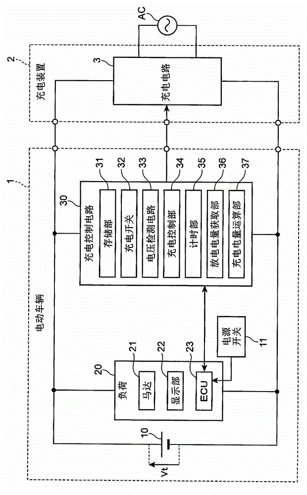
[0029] figure 1 It is a block diagram showing when an electric vehicle according to an embodiment of the present invention is connected to a charging device. figure 1 The illustrated electric vehicle 1 includes a lead storage battery 10 , a power switch 11 , a load 20 , and a charging control circuit 30 according to an embodiment of the present invention. The lead storage battery 10 supplies electric power to each part of the electric vehicle 1 . The power switch 11 turns on and off the power of the electric vehicle 1 . The power switch 11 turns on the power of the electric vehicle 1 when the operator inserts the key, for example, and turns off the power when the key is pulled out. The load 20 includes a motor 21 , a display unit 22 , and an electronic control unit (ECU) 23 . The motor 21 functions as a driving source for moving the vehicle. The display unit 22 ...
Embodiment 1-1
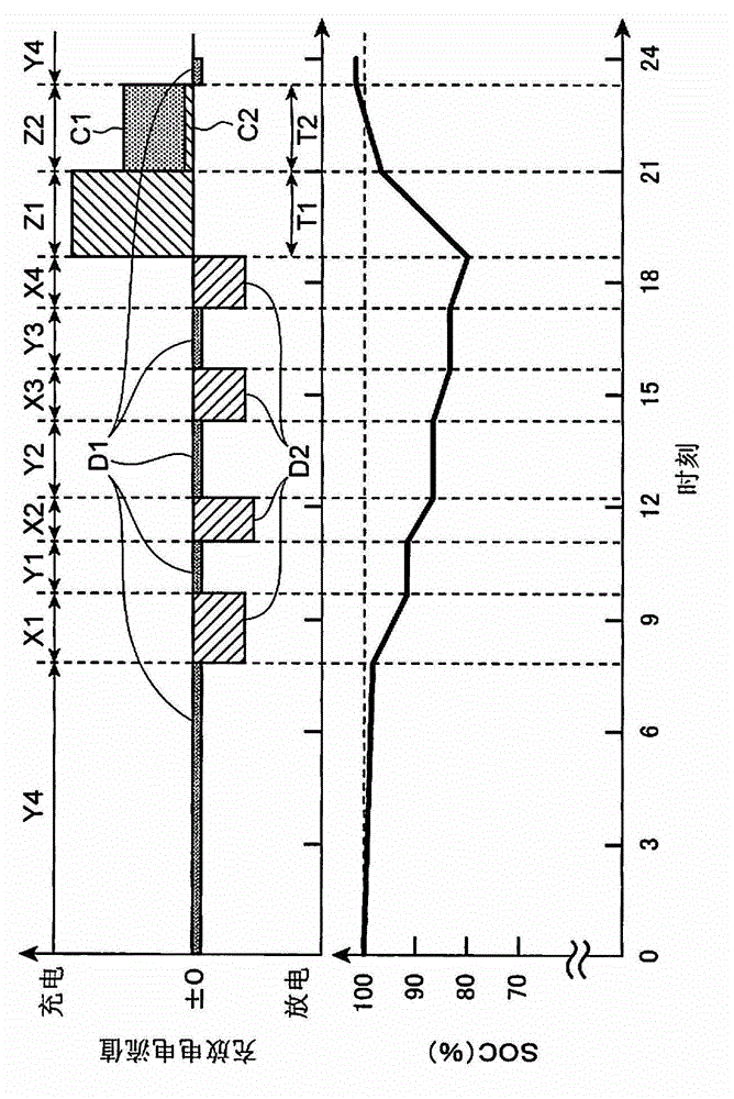
[0059] As described above, as in Comparative Example 1-1, two stages of constant current charging were performed after each discharge mode L to N. FIG. However, in Example 1-1, as shown in the above description of the embodiment, the total discharged electric quantity D is divided into the second discharged electric quantity D2 in the drive periods X1 to X4 and the first discharged electric quantity D1 in the rest periods Y1 to Y4. . Furthermore, the charged electric quantity C is the first charged electric quantity C1 obtained by multiplying the first discharged electric quantity D1 by 1.5 which is the first coefficient α, and the second charged electric quantity C2 obtained by multiplying the second discharged electric quantity D2 by 1.1 which is the second coefficient β. Sum to find out. Except for this, charging and discharging were repeated in the same manner as in Comparative Example 1-1. The transition of the discharge capacity measured in the same manner as in Compar...
Embodiment 1-2
[0062] In Example 1-2, compared to Example 1-1, the value of the first coefficient α for calculating the charge electric quantity C in each of the discharge modes L to N is made different from each other. That is, in Embodiment 1-2, the first coefficient α is set to 1.2 during the discharge mode L, the first coefficient α is set to 1.5 during the discharge mode M, and the first coefficient α is set to 1.9 during the discharge mode N. Out of charging capacity C. Except for this, charging and discharging were repeated in the same manner as in Example 1-1. The transition of the discharge capacity measured in the same manner as in Comparative Example 1-1 is also described in Figure 6 middle.
[0063] In addition, regarding the charging conditions, unlike Example 1-1, the larger the calculated value of the first charged electric quantity C1 is, the longer the charging time (charging time T2) of the second stage which is the last stage is.
[0064] Depend on Figure 6 It was cl...
PUM
 Abstract
Description
Claims
Application Information
 - R&D
- Intellectual Property
- Life Sciences
- Materials
- Tech Scout
- Unparalleled Data Quality
- Higher Quality Content
- 60% Fewer Hallucinations
Browse by: Latest US Patents, China's latest patents, Technical Efficacy Thesaurus, Application Domain, Technology Topic, Popular Technical Reports.
© 2025 PatSnap. All rights reserved.Legal|Privacy policy|Modern Slavery Act Transparency Statement|Sitemap|About US| Contact US: help@patsnap.com


