

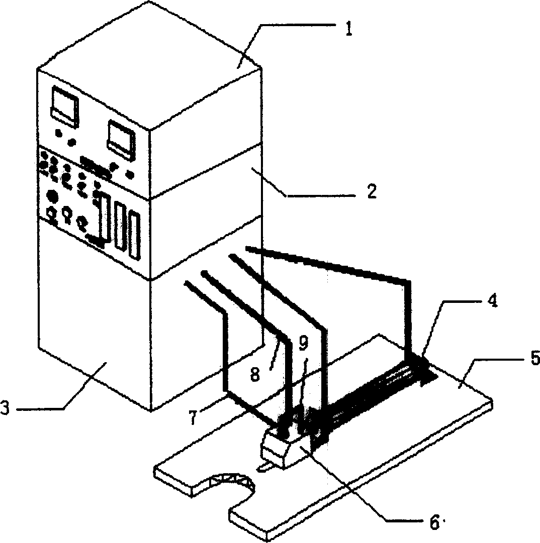
Powder metallurgy static mould wall lubricating device
A mold wall lubrication and powder metallurgy technology, applied in the field of powder metallurgy, can solve the problems of use, high cost, limited selection of lubricating powder, etc., and achieve the effect of great flexibility and easier maintenance.
- Summary
- Abstract
- Description
- Claims
- Application Information
AI Technical Summary
Problems solved by technology
Method used
Image

Examples
example 1
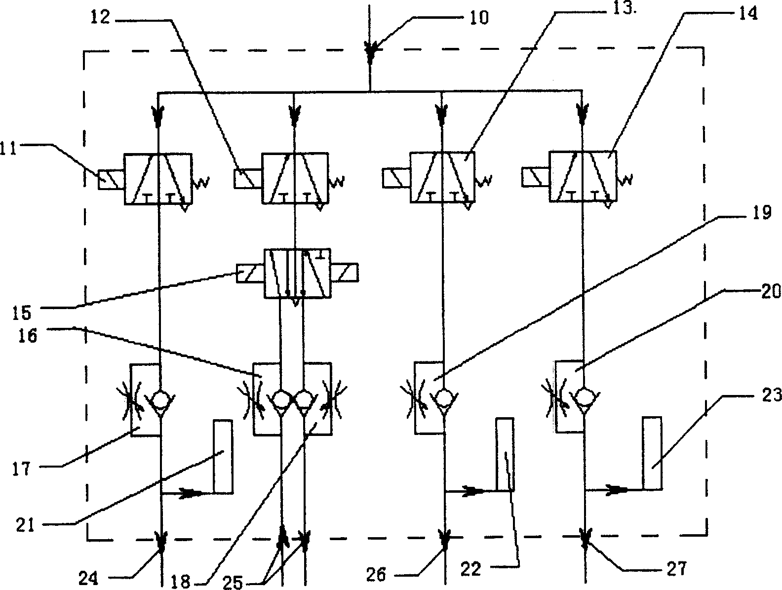
[0046] Example 1: Determination of the required amount of charge that the new electrostatic mold wall lubrication device can bring to each lubricating powder by means of corona discharge. Set the device with a voltage of 12KV as an example, each spraying time does not exceed 1 second, the powder spraying wind pressure is about 0.6MPa, and the length of the powder delivery hose is 1m. Use an electronic analytical balance (accuracy: 0.0001g) to measure the mass of the lubricating powder, and calculate the charge-to-mass ratio of the lubricating powder. The results are shown in the table below:
[0047]
lubricant powder
EBS wax
w-special
the wax
compound run
powder one
compound run
slippery powder two
compound run
slip powder three
compound run
Slippery powder four
compound run
Slippery five
charge to mass ratio
(μc / g)
0.166
...
example 2
[0050] Example 2: Spray lubricating powder on the inner wall of the mold with this new type of electrostatic mold wall lubrication equipment, and press 316L stainless steel powder (fineness: ≤74μm) by using external lubrication or a combination of internal and external lubrication under room / temperature pressure. At 680MPa, measure the green compact density with the micrometer method. The results of each experiment are shown in the table below:
[0051] to lubricate
Way
Internal lubrication
0.2% W-special wax
0.2% EBS wax
none
External lubrication
Compound lubricant powder six
Compound Lubricating Powder II
EBS wax
EBS wax
EBS wax
Pressed powder heating temperature
(℃)
120
120
120
120
120
120
120
110
mold heating temperature
(℃)
1...
PUM
 Abstract
Description
Claims
Application Information