Feeding device in centrifugal machine

A centrifuge and feeder technology, which is applied in the field of feeders, can solve problems such as power consumption, heavy load, and centrifuge vibration, and achieve the effects of cost reduction, simple structure, and simplified structure

Inactive Publication Date: 2012-10-17
苏州盛天力离心机制造有限公司
View PDF7 Cites 12 Cited by
  • Summary
  • Abstract
  • Description
  • Claims
  • Application Information

AI Technical Summary

Problems solved by technology

[0002] Most of the feeding devices used in the existing scraper centrifuges are pot-cover-shaped distributing plates located above the main shaft, or feeding pipes located on the inner side of the drum. Inside the drum of the centrifuge, a lot of materials will be unevenly distributed, which will cause the centrifuge to appear unbalanced during operation, causing the centrifuge to vibrate
[0003] In recent years, there has been a motor-driven feeder installed on the cover plate of the centrifuge shell. Although it can more evenly spread the material on the drum wall of the centrifuge, it still has the following disadvantages: 1. Power consumption is required; 2. The burden on the shell cover of the centrifuge is increased. The load of the shell cover of the centrifuge is already very heavy due to the installation of the scraper box. In addition, the installation of the distributor with a motor drive makes the cover The burden of the centrifuge is even heavier. When the cover of the shell needs to be opened, it must be assisted by a hydraulic cylinder, which makes the structure of the whole centrifuge more complicated and the cost is higher.

Method used


Image

  • Feeding device in centrifugal machine
  • Feeding device in centrifugal machine

Examples


Embodiment Construction

[0015] The feeder in the centrifuge of the present invention will be described in further detail below through specific examples.

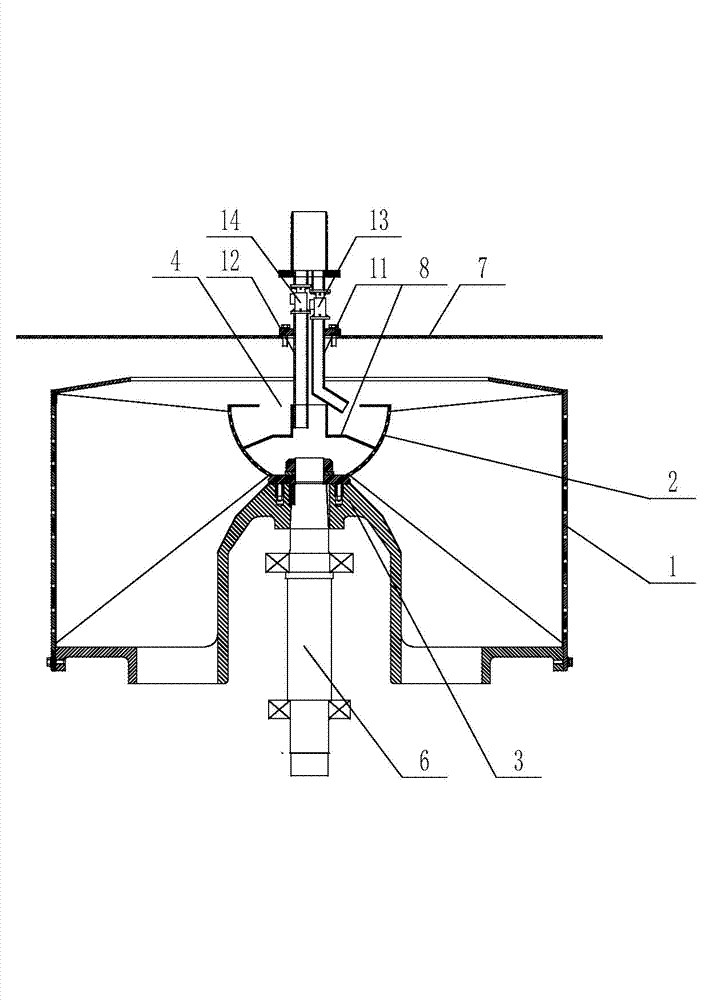
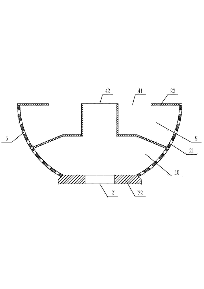
[0016] Such as figure 1 , figure 2 As shown, the feeder in the centrifuge includes a feed bin 2 arranged inside the drum 1 of the centrifuge, the feed bin 2 is fixed to the drum seat 3 of the centrifuge, and the top of the feed bin 2 is arranged There is a material inlet 4, and the side wall 21 of the material broadcasting bin 2 is an outwardly protruding arc surface, and the side wall 21 of the material broadcasting bin 2 is distributed with discharge holes 5.

[0017] As a preferred solution, the side wall 21 of the sowing bin 2 is a partial spherical surface, and the sowing bin 2 is coaxially arranged with the main shaft 6 of the centrifuge. This allows for more uniform sowing.

[0018] The feeding port 4 of the sowing bin 2 is provided with a feeding pipe, the feeding pipe is arranged on the cover plate 7 of the centrifuge shell, the feedi...


PUM


Abstract

The invention relates to a feeding device in a centrifugal machine. The feeding device comprises a feeding bin which is arranged in a rotary drum of the centrifugal machine, wherein the feeding bin is fixedly connected with a rotary drum seat of the centrifugal machine; a feeding opening is arranged at the top of the feeding bin; the side wall of the feeding bin is a convex arc surface; and discharging holes are distributed on the side wall of the feeding bin. The feeding device in the centrifugal machine, disclosed by the invention, is suitable for the centrifugal machine and can uniformly feed materials.

Description

technical field [0001] The invention relates to the technical field of centrifuges, in particular to a feeder in a centrifuge. Background technique [0002] Most of the feeding devices used in the existing scraper centrifuges are pot-cover-shaped distributing plates located above the main shaft, or feeding pipes located on the inner side of the drum. Inside the drum of the centrifuge, a lot of materials will be unevenly distributed, which will cause the centrifuge to appear unbalanced during operation and cause the centrifuge to vibrate. [0003] In recent years, there has been a motor-driven feeder installed on the cover plate of the centrifuge shell. Although it can more evenly spread the material on the drum wall of the centrifuge, it still has the following disadvantages: 1. Power consumption is required; 2. The burden on the shell cover of the centrifuge is increased. The load of the shell cover of the centrifuge is already very heavy due to the installation of the scr...

Claims


Application Information

Patent Timeline
Patent Type & Authority Applications(China)
IPC IPC(8): B04B11/02
Inventor 陈志才
Owner 苏州盛天力离心机制造有限公司
Why Eureka
Try Eureka