Lock cylinder post-machining device

A technology for processing devices and lock cylinders, which is applied in the direction of sawing machine devices, metal processing, metal processing equipment, etc., can solve the problems of affecting the rigidity of lock cylinders, low processing accuracy, and high material costs, so as to achieve convenient operation, ensure processing accuracy, and equipment The effect of simple structure

Inactive Publication Date: 2012-10-17
温岭市铭创机床有限公司
View PDF7 Cites 5 Cited by
  • Summary
  • Abstract
  • Description
  • Claims
  • Application Information

AI Technical Summary

Problems solved by technology

[0002] Now locks play an indispensable role in daily life, and the quality of the locks determines whether our lives and property can be guaranteed. One of the important factors is that people's dependence on locks continues to increase, and their The demand for quantity is also increasing day by day, and the material of the lock cylinder is copper, and its material cost is very high. Therefore, the amount of material determines its cost and quality. Excess copper material is cut off on the core to reduce the cost of the lock core. In the industry, it is called the material stealing process, that is, the post-processing process of the lock core. The current process is post-processing through the manual lock core, but manual The processing accuracy is low. When the amount of stolen material is too much, the rigidity of the lock cylinder will decrease or even be scrapped. At the same time, the place where the material is stolen is asymmetrical, which also affects the rigidity of the lock cylinder, and manual operation is required. Low efficiency, operators are easily injured, etc.

Method used


Image

  • Lock cylinder post-machining device
  • Lock cylinder post-machining device
  • Lock cylinder post-machining device

Examples


Embodiment Construction

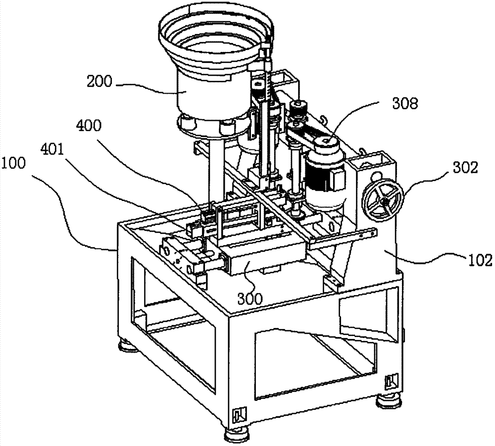
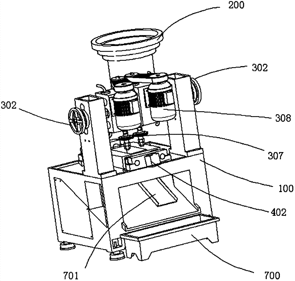
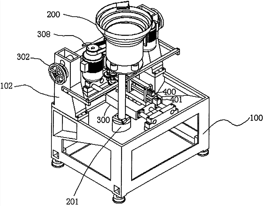
[0020] refer to Figure 1-Figure 7 A post-processing device for a lock cylinder, comprising a main body support, a positioning and material setting device, a monolithic device and two knife seats 306, wherein the knife seats 306 include two saw blades 307 and a motor 308 placed on both sides of the knife seat 306, and The saw blade 307 is connected to the motor 308; the monolithic device includes a vibrating disc 200, a vibrating motor 201 and a material guide rod, the vibrating motor 201 is fixedly connected to the vibrating disc 200 and the main body bracket 100 respectively, and the discharge port of the vibrating disc 200 and the upper material guide The rod 601 is connected; the position-fixing material device includes a limit feeding mechanism, a slide table 300, a feeding mechanism and a control electric board. The slide table 300 is slidably connected to the main body bracket through a guide rail, and the limit feed mechanism is placed on the upper guide rod 601 and co...


PUM


Abstract

The invention discloses a lock cylinder post-machining device, which comprises a main body bracket, a blocking setting device, a finishing device and tool aprons, wherein the finishing device comprises a vibrating tray, a vibrating motor and a guide rod; the vibrating motor is respectively fixedly connected with the vibrating tray and a base bracket, and the guide rod is arranged below a discharge hole of the vibrating tray; the blocking setting device comprises a limit discharging mechanism, a sliding table, a feeding mechanism and a control electric plate; and the sliding table is connected with the base bracket through a guide rail in a sliding mode, a workpiece enters the sliding table from the guide rod through the limit discharging mechanism, and the feeding mechanism is arranged on the main body bracket, so that the workpiece on the sliding table is machined close to a cutter. According to the device, full-automatic machining of a lock cylinder is realized through the finishing mechanism, the limit discharging mechanism, the blocking setting device and the cutter; by matching the control electric plate, efficient and high-precision machining of the lock cylinder is realized; due to reasonable structural design of parts, the whole device is simple in structure; through a control system of the control electric plate, the device is convenient to operate; and through an adjusting system of the tool aprons, the machining precision of the lock cylinder is ensured.

Description

technical field [0001] The invention relates to the field of lock cylinder processing, in particular to a high-efficiency lock cylinder post-processing equipment which realizes mechanical properties through a cylinder. Background technique [0002] Now locks play an indispensable role in daily life, and the quality of the locks determines whether our lives and property can be guaranteed. One of the important factors is that people's dependence on locks continues to increase, and their The demand for quantity is also increasing day by day, and the material of the lock cylinder is copper, and its material cost is very high. Therefore, the amount of material determines its cost and quality. Excess copper material is cut off on the core to reduce the cost of the lock core. In the industry, it is called the material stealing process, that is, the post-processing process of the lock core. The current process is post-processing through the manual lock core, but manual The processi...

Claims


Application Information

Patent Timeline
Patent Type & Authority Applications(China)
IPC IPC(8): B23D47/00B23D47/04B23Q7/00
Inventor 余庭发张健
Owner 温岭市铭创机床有限公司
Why Eureka
Try Eureka