Robot system

A robot system and robot technology, applied in the field of robot systems, can solve problems such as the inability of robot systems to emit laser beams

Inactive Publication Date: 2012-10-17
YASKAWA DENKI KK
View PDF10 Cites 9 Cited by
  • Summary
  • Abstract
  • Description
  • Claims
  • Application Information

AI Technical Summary

Problems solved by technology

[0003] Although the robot system according to Japanese Patent Laid-Open No. 2008-43971 can emit a laser beam to a processing trajectory of an arbitrary shape in a state where the laser emitting device (laser emitting part) is positioned (st...

Method used


Image

  • Robot system
  • Robot system
  • Robot system

Examples


Embodiment Construction

[0022] The embodiments of the present invention will now be described with reference to the drawings.

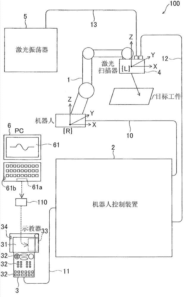
[0023] First, refer to Figure 1 to Figure 3 The structure of the robot system 100 according to the embodiment of the present invention is described.

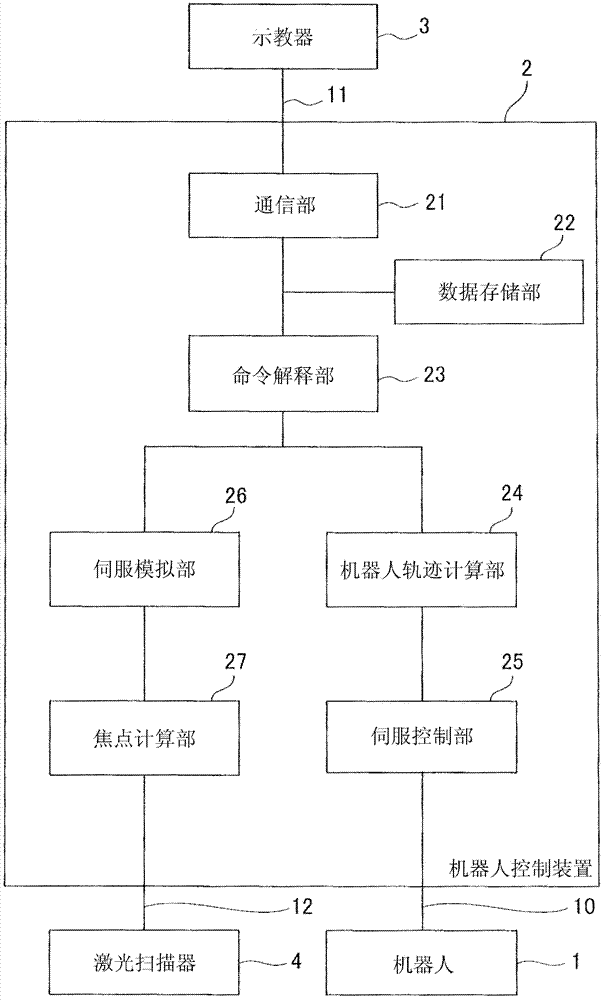
[0024] The robot system 100 according to the embodiment of the present invention is a robot system for remote laser welding, which emits a laser beam from a position spaced apart from a target workpiece (for example, a position spaced about 500 mm apart) to perform laser welding. The robot system 100 includes a robot 1, a robot control device 2 that controls the robot 1, and a teach pendant (programmed teach pendant) 3 that teaches the operation of the robot 1, such as figure 1 Shown in. The robot system 100 according to this embodiment further includes a laser scanner 4 for emitting a laser beam installed on the robot 1 and a laser oscillator 5 that supplies the laser beam to the laser scanner 4. The teaching pendant 3 is an exa...


PUM


Abstract

This robot system (100) includes a robot (1), a laser emitting portion (4) moved by the robot, emitting a laser beam to a target workpiece, and a control portion (27) controlling the laser emitting portion to emit the laser beam on the basis of information regarding an arbitrarily-shaped work locus and movement information of the laser emitting portion.

Description

Technical field [0001] The present invention relates to a robot system, and more specifically, to a robot system including a laser emitting part capable of emitting a laser beam. Background technique [0002] Robot systems including a laser emitting section capable of emitting laser beams are widely known. Japanese Patent Laid-Open No. 2008-43971 discloses a robot system including a laser emitting device (laser emitting section) capable of emitting a laser beam to a target workpiece. The robot system is formed to emit a laser beam to a processing track of an arbitrary shape in a state where the laser emitting device is positioned (stayed) at a specified position. [0003] Although the robot system according to Japanese Patent Laid-open No. 2008-43971 can emit a laser beam to a processing trajectory of any shape while the laser emitting device (laser emitting part) is positioned (stayed) at a specified position, there may be such a problem That is, when the laser emitting device (...

Claims


Application Information

Patent Timeline
IPC IPC(8): B23K26/08B23K26/00
CPCB23K26/0807B25J9/1664B23K26/0884B23K26/08Y10S901/41B23K26/082
Inventor 大江裕树牧野圭司
Owner YASKAWA DENKI KK
Why Eureka
Try Eureka