
Angle ejection device for injection mold

A technology of injection mold and inclined roof, which is applied in the field of plastic injection molding to avoid the effect of screw breaking

Inactive Publication Date: 2012-10-17
毅昌金型(东莞)五金制品有限公司
View PDF6 Cites 5 Cited by
  • Summary
  • Abstract
  • Description
  • Claims
  • Application Information

AI Technical Summary

Problems solved by technology

[0005] The further technical problem to be solved by the present invention is to provide an improved tilting jack device that prevents the tilting jack from being completely reset due to the deformation of the needle plate.

Method used


Image

  • Angle ejection device for injection mold
  • Angle ejection device for injection mold
  • Angle ejection device for injection mold

Examples


Embodiment Construction

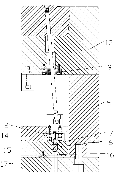
[0023] as attached Figures 1 to 4 As shown, the injection mold generally includes an upper template (not shown in the figure), a lower template 13, a square iron 5 supporting the lower template 13, a bottom plate 17, a bottom needle plate 15 and a face needle plate 14 for installing ejector pins. The inclined roof device disclosed in this embodiment mainly includes two major parts: an inclined roof installation part and an inclined roof 8, wherein the inclined roof installation part includes an inclined roof box 1 and an inclined roof box seat 3, and the inclined roof installation part is divided into an inclined roof box 1 and slanted top box seat 3 are mainly to facilitate processing and assembly. The slanted top box 1 and the slanted top box seat 3 are fixedly connected together by screws 4 . The lower end of the inclined top 8 cooperates with the inclined top box 1 , and the inclined top 8 is rotatable and laterally slidable relative to the inclined top box 1 through the...


PUM

PropertyMeasurementUnit
heightaaaaaaaaaa
heightaaaaaaaaaa

Abstract

The invention discloses an angle ejection device for an injection mold. The angle ejection device comprises an angle ejection and an angle ejection mounting portion. The angle ejection slides relatively to the angle ejection mounting portion and is rotatablely arranged on angle ejection mounting portion; the angle ejection mounting portion is arranged between a face needle plate and a bottom needle plate of the injection mold; the bottom needle plate is provided with a light hole and a limit screw passing through the light hole, and the front end of the limit screw is fixedly connected to the angle ejection mounting portion; and a polish rod of the limit screw is sleeved with a compression spring, which is positioned between the bottom of the light hole and the head of the limit screw, or positioned between the bottom of the bottom needle plate and the head of the limit screw. According to the angle ejection device for the injection mold provided by the invention, the compression spring is sleeved on the limit screw to exert certain pretension on the angle ejection mounting portion; and when the angle ejection device can not reset accurately due to thermal expansion and cold contraction, certain buffer of the angle ejection device can be ensured, so as to avoid problems of screw snap or angle ejection breaking.

Description

technical field [0001] The invention relates to the technical field of plastic injection molding, in particular to an inclined roof device for injection molds. technical background [0002] The inclined top device is widely used in the field of plastic molds. The inclined top device is usually suitable for the small size barb structure that is ejected from the inner side of the product. It includes a slanted top, a slanted top box seat, and a slanted top box (the slanted top box seat and the slanted top box are combined to form a slanted top installation part), the slanted top is set on the sloping top seat, and the slanted top can slide and move relative to the slanted top. Rotately installed on the inclined top box. After the movable mold and the fixed mold are opened, under the action of the longitudinal movement of the needle plate, the inclined top slides horizontally to avoid the barbs and other structures inside the product, and implement smooth demoulding. Howeve...

Claims


Application Information

Patent Timeline
Patent Type & Authority Applications(China)
IPC IPC(8): B29C45/40
Inventor 陈锦华曾秋文邓贵华冯仕煌
Owner 毅昌金型(东莞)五金制品有限公司
Learn More